Fingerprint reverser with handle

A handle and fingerprint technology is applied to the reversing of fingerprints with a handle. It can solve the problems of troublesome disassembly of the handle, easy wrong installation of parts, troublesome installation, etc., to achieve the effect of convenient operation, simple reversing, and reduction of inventory quantity

Inactive Publication Date: 2019-01-01
深圳市优点科技有限公司
6 Cites 0 Cited by

AI-Extracted Technical Summary

Problems solved by technology

[0004] 1. Fix the handle with screws to change the installation method, it is troublesome to disassemble the handle (thread glue has been applied), and thread glue is required during installation, which is troublesome to install, requires professional personnel to operate, and has certain risks
[0005] 2. Use nuts to fix the handle and change the left and right installation methods. It is troublesome to disassemble the handle (the pressing piece has been positioned), and t...

Abstract

The invention discloses a fingerprint reverser with a handle. The fingerprint reverser with the handle comprises a front handle decorative cover, a fingerprint identification module, a handle siliconepad, a handle lamp panel, a connecting wire, a wire pressing plate, a handle, a planar bearing assembly, a handle decorative cover, a front locking surface, a wavy gasket, a handle return spring, a wire clamp, a fingerprint head wire, a handle limiting cover, a handle rotary head, a square steel spring, square steel and a bolt, wherein the fingerprint identification module is embedded into the inner side of a circular slot in the right side of the front handle decorative cover; the handle silicone pad is arranged at the front end of the front handle decorative cover; when the handle limitingcover does not have a limiting function, the limiting refers to loosening a bolt through the handle rotary head; when the bolt is loosened, the handle can automatically rotate, so that the handle canrotate to a needed direction; the back surface of the handle rotary head is provided with an avoiding part, so that the connecting wire is not rubbed when the handle is rotated and reversed; and moreover, the fingerprint reverser with the handle is simple in reversing, is free of risk after reversing, does not need a professional to operate, can stock up in all directions, and can reduce quantityin stock.

Application Domain

Building locksHandle fasteners

Technology Topic

FingerprintEngineering +1

Image

  • Fingerprint reverser with handle
  • Fingerprint reverser with handle
  • Fingerprint reverser with handle

Examples

  • Experimental program(1)

Example Embodiment

[0031] The following will be combined with Figure 1-3 The present invention is described in detail, and the technical solutions in the embodiments of the present invention are clearly and completely described. Apparently, the described embodiments are only some of the embodiments of the present invention, not all of them. Based on the embodiments of the present invention, all other embodiments obtained by persons of ordinary skill in the art without making creative efforts belong to the protection scope of the present invention.
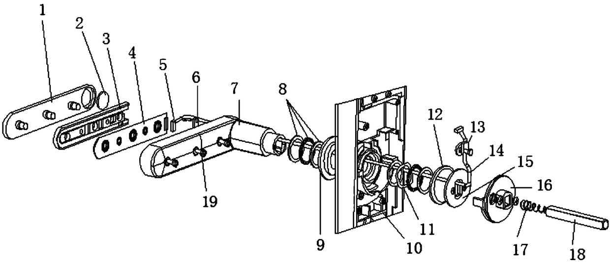
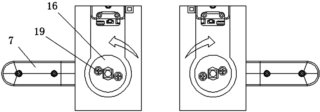
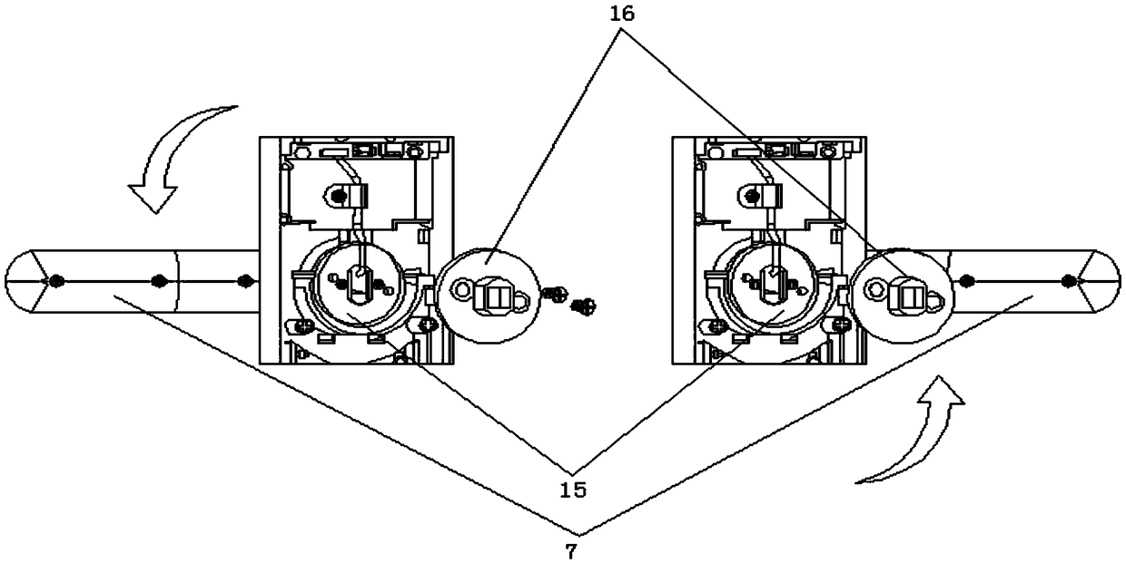
[0032] The present invention provides a fingerprint reversing with a handle through improvement, including a front handle decorative cover 1, a fingerprint recognition module 2, a handle silicone pad 3, a handle light board 4, a connecting line 5, a pressure plate 6, a handle 7, a plane Bearing assembly 8, handle decorative cover 9, front lock surface 10, wave washer 11, handle return spring 12, wire clamp 13, fingerprint head line 14, handle limit cover 15, handle turning head 16, square steel spring 17, square Steel 18 and screw 19, the fingerprint recognition module 2 is embedded in the inside of the circular groove on the right side of the front handle decoration cover 1, the handle silicone pad 3 is arranged on the front end of the front handle decoration cover 1, and the inner through hole is connected with the front end column of the front handle decoration cover 1 Inserting, the handle light board 4 is bonded to the front end of the handle silicone pad 3, the connecting wire 5 and the rear end are inserted into the gap at the right end of the handle silicone pad 3, and the front end is bonded to the right side of the rear end of the handle 7, and the crimping plate 6 is welded to the handle 7 In the middle of the rear end, the front end of the plane bearing assembly 8 is embedded in the rear end of the handle decoration cover 9, the front end of the handle decoration cover 9 is embedded in the middle of the rear end of the front lock surface 10, and the wave gasket 11 is arranged between the plane bearing assembly 8 at the front end of the front lock surface 10 In between, the rear end of the handle return spring 12 is bonded to the front side surface of the plane bearing assembly 8 at the front end of the front lock surface 10, and the rear end of the fingerprint head line 14 passes through the handle 7, the plane bearing assembly 8, the handle decoration cover 9, and the front lock surface 10 , the wave gasket 11 and the handle return spring 12 are inserted into the right side of the connecting line 5, the wire clip 13 is bonded to the top of the front end of the fingerprint head line 14, the rear end surface of the handle limit cover 15 is bonded to the front end of the handle return spring 12 The left and right ends of the handle turning head 16 are embedded in the left and right sides of the middle part of the front lock surface 10, and the rear end is bonded to the front surface of the handle limit cover 15, and the square steel 18 is inserted into the middle of the handle turn head 16 and the middle part of the handle limit cover 15. In the groove, the square steel spring 17 is welded on the square steel 18 rear end, and the left side of the handle 7 front end, the left and right sides of the handle limit cover 15 and the left and right sides of the handle turning head 16 are all provided with screws 19 .
[0033] There are three planar bearing assemblies 8 arranged respectively from front to back for bonding.
[0034] The screws 19 are provided with seven.
[0035] The handle 7 can be rotated 180 degrees.
[0036] The handle limiting cover 15 is circular.
[0037] The present invention provides a fingerprint commutation with a handle through improvement, which operates in the following manner;
[0038] First, the screw 19 at the front end of the handle turning head 16 is rotated and removed;
[0039] Second, then rotate the handle 7 180 degrees:
[0040] The 3rd, rotate and fix 2 screws 19 on the handle rotating head 16 again, just complete right-left interchange.
[0041] The present invention provides a fingerprint reversing with a handle through improvement. When the handle limit cover 15 does not have a limit function, the limit is through the handle turning head 16. When the screw 19 is loosened, the handle 7 can rotate by itself and can turn To the direction we need, and the back of the handle turning head 16 has a void, so that the handle 7 will not rub the connecting line 5 when turning and changing directions, and the changing direction is simple, there is no risk after changing the direction, and it can be operated without professionals , At the same time, stocking is not divided into left and right, which can reduce the number of stocks.
[0042] A kind of fingerprint reversing with handle of the present invention, reversing is simple, easy to operate, only need to remove 2 screws 19, handle 7 can rotate 180 degrees and fix, then screw 19 can complete reversing.
[0043] The fingerprint reversing with handle of the present invention requires a Phillips screwdriver, which is a commonly used standard tool.
[0044] The fingerprint reversing with a handle described in the present invention does not need to disassemble the cover plate, and will not rub the wire, and there is no risk after reversing, and no professional operation is required.
[0045] The fingerprint reversing with a handle of the present invention can be prepared regardless of left and right, and can reduce the inventory quantity.
[0046]The above description of the disclosed embodiments is provided to enable any person skilled in the art to make or use the invention. Various modifications to these embodiments will be readily apparent to those skilled in the art, and the general principles defined herein may be implemented in other embodiments without departing from the spirit or scope of the invention. Therefore, the present invention will not be limited to the embodiments shown herein, but is to be accorded the widest scope consistent with the principles and novel features disclosed herein.

PUM

no PUM

Description & Claims & Application Information

We can also present the details of the Description, Claims and Application information to help users get a comprehensive understanding of the technical details of the patent, such as background art, summary of invention, brief description of drawings, description of embodiments, and other original content. On the other hand, users can also determine the specific scope of protection of the technology through the list of claims; as well as understand the changes in the life cycle of the technology with the presentation of the patent timeline. Login to view more.

Similar technology patents

Household appliance control method and device and mobile terminal

InactiveCN103605531Aeasy to operateeasy to use
Owner:GD MIDEA AIR-CONDITIONING EQUIP CO LTD +1

Graphene film and preparation method therefor

Owner:CHANGZHOU FUXI TECH CO LTD

Driving working load calculation method of automobile driver

InactiveCN101690666AImprove accuracy and timelinessEasy to operate
Owner:BEIJING UNIV OF TECH

Laser radar optical system with optical axis calibrating function and optical axis calibrating method

InactiveCN102353950AOptical axis alignment with high precisioneasy to operate
Owner:INST OF APPLIED ELECTRONICS CHINA ACAD OF ENG PHYSICS +1

Classification and recommendation of technical efficacy words

  • easy to operate

Lancet device

InactiveUS7303573B2inexpensively mass-producedeasy to operate
Owner:ABBOTT DIABETES CARE INC

Rapid and non-invasive optical detection of internal bleeding

InactiveUS20050065436A1easy to operaterapid and accurate result
Owner:HO WINSTON ZONH +2
Why Eureka
Try Eureka