Sliding door travel control system

A travel control, sliding door technology, applied in the control system, motor generator control, door/window accessories, etc., can solve the problems of the travel switch requiring wiring, the high price of the control part, troublesome installation and maintenance, etc., to avoid system failure, The effect of improving reliability and service life, reducing manufacturing and maintenance costs

Pending Publication Date: 2019-01-01
谢仲辉
View PDF0 Cites 0 Cited by
  • Summary
  • Abstract
  • Description
  • Claims
  • Application Information

AI Technical Summary

Problems solved by technology

The control method using stepper motor has relatively high precision, but the price of the control part is also relatively high
In the control method using the limit switch, because the limit switch is a mechanical device, it is easy to fail after a long time, and the limit switch needs to be wired, and the installation and maintenance are more troublesome.

Method used


Image

  • Sliding door travel control system
  • Sliding door travel control system
  • Sliding door travel control system

Examples


Embodiment Construction

[0018] The present invention is further described below in conjunction with embodiment.

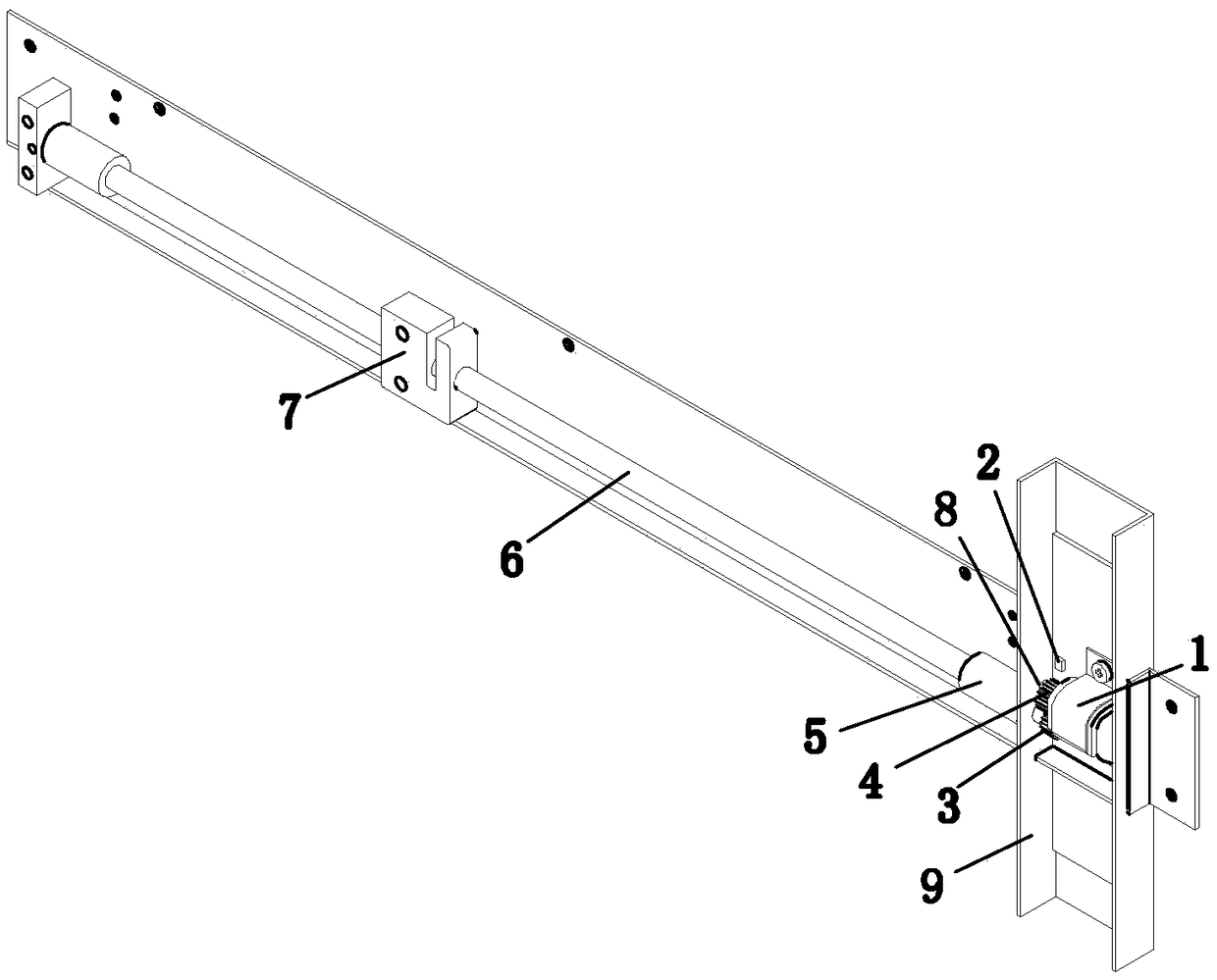
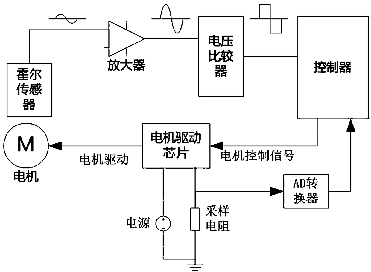
[0019] Such as figure 1 and figure 2 A sliding door stroke control system is shown, which includes a linear transmission mechanism, a motor 1, a magnet 8, a Hall sensor 2, and an electrical control circuit. The sliding door here is installed on sliding door installation structures such as cabinets and door frames. , the sliding door here can be a car door, cabinet door, room door and window, etc. The linear transmission mechanism is a mechanism that converts the rotation of the motor into a linear motion. The motor 1 drives the sliding door to move through the linear transmission mechanism, and the motor 1 also drives the magnet 8 to rotate. The Hall sensor 2 is used to sense the change of the magnetic field of the magnet 8 , and the magnet induction signal output end of the Hall sensor 2 and the motor 1 are respectively electrically connected to the electrical control circuit.

[0020...


PUM


Abstract

The invention discloses a sliding door travel control system. A sliding door is slidingly mounted; the system comprises a linear transmission mechanism, a motor, a magnet, a hall sensor and an electric control loop; the motor drives the sliding door to move through the linear transmission mechanism, and drives the magnet to rotate; the hall sensor is used for inducing the magnetic field change ofthe magnet; and a magnet induction signal output end of the hall sensor and the motor are electrically connected with the electric control loop. The sliding door travel control system is high in reliability and long in service life.

Description

technical field [0001] The invention relates to a sliding door stroke control system. Background technique [0002] The currently widely used mechanism of the screw slider driven by a motor usually uses a stepping motor as a stroke control method, or uses a travel switch at both ends of the slider to limit the travel range of the slider. The control method using a stepping motor has relatively high precision, but the price of the control part is also relatively high. In the control method using the limit switch, since the limit switch is a mechanical device, it is easy to fail after a long time, and the limit switch needs wiring, and the installation and maintenance are also troublesome. Contents of the invention [0003] The technical problem to be solved by the present invention is to provide a sliding door stroke control system with high reliability and long service life. [0004] To solve the problems of the technologies described above, the technical scheme adopted ...

Claims


Application Information

Patent Timeline
IPC IPC(8): E05F15/652H02P8/00H02H7/093
CPCH02H7/093H02P8/005E05F15/652E05Y2900/20E05Y2900/531E05Y2900/132
Inventor 谢仲辉
Owner 谢仲辉
Why Eureka
Try Eureka