Optical fiber communication system capable of monitoring multiple mining conveyor belts

An optical fiber communication system and conveyor belt technology, applied in transmission systems, signal transmission systems, electromagnetic wave transmission systems, etc., can solve the problems of complex electromagnetic environment, easy to be interfered, and large interference, achieve high data transmission rate, avoid system failure, Good anti-interference effect

Inactive Publication Date: 2010-06-30
SHANGHAI UNIV +1
View PDF0 Cites 0 Cited by
  • Summary
  • Abstract
  • Description
  • Claims
  • Application Information

AI Technical Summary

Problems solved by technology

However, the system also has certain limitations: 1. Twisted-pair copper wires are used as the signal transmission medium, and the anti-interference ability is poor. Because there are various large-scale construction machinery and motors and other strong electric equipment in the mine, the electromagnetic environment in the mine is complicated and interferes. Large, and because the mine is very long, the twisted pair often needs to be extended for more than ten kilometers, which makes the signal seriously distorted and more susceptible to interference, so the reliability of signal transmission is very poor; 2. The transmission rate of the twisted pair modulation and demodulation mode is low, It cannot adapt to the transmission of large amounts of data; 3. The single-chip microcomputer system is located underground, which requires high anti-interference ability of software and hardware; 4. This twisted pair modulation and demodulation method is only suitable for point-to-point signal transmission, so a monitoring computer Can only monitor one belt, not suitable for mines with multiple conveyor belts
[0005] can be used figure 2 Program pair figure 1 The conveyor belt monitoring system shown is transformed into optical fiber, figure 2 The optical modules 9 and 10 are used to replace the modems 6 and 7, and the transmission medium is also changed from twisted pair to optical fiber. This solution can improve the anti-interference performance of the system, but because the serial port communication is still used, the transmission rate cannot be improved and cannot be used effectively. The bandwidth advantage of optical fiber, and it is only suitable for one-to-one monitoring

Method used


Image

  • Optical fiber communication system capable of monitoring multiple mining conveyor belts
  • Optical fiber communication system capable of monitoring multiple mining conveyor belts
  • Optical fiber communication system capable of monitoring multiple mining conveyor belts

Examples


Embodiment Construction

[0020] A preferred embodiment of the optical fiber communication system capable of monitoring a plurality of mine conveyor belts is described in detail as follows:

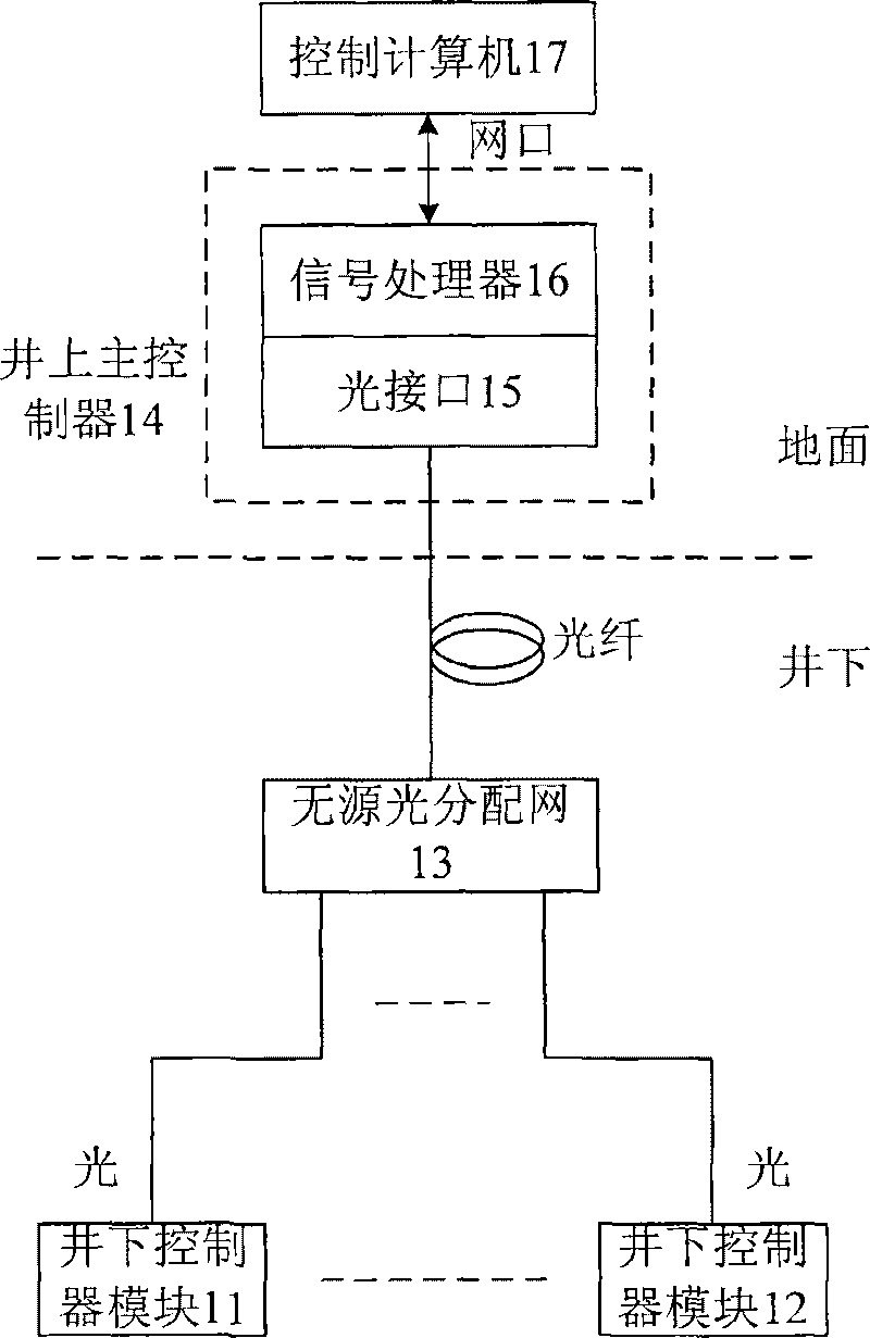
[0021] see image 3 , in the uplink direction, an optical signal of a certain wavelength (generally 1310 nm) sent by the downhole control modules 11 and 12 is sent to the uphole master controller 14 through the passive optical splitter 13 . Since there are multiple downhole control modules sharing one wavelength, the downhole control modules should send optical signals in time-sharing, and which downhole control module sends the signal is determined by the uphole main controller, ensuring that no conflicts will occur. The main controller on the well sends the downhole control module signal received by the optical interface 15 to the control computer 17 through the Ethernet port for storage and processing after being processed by the data processor 16 .

[0022] In the downlink direction, after the control signal ...


PUM


Abstract

The invention relates to an optical fiber communication system which can detect a plurality of mining conveyor belts, comprising an underground control module, a no-source optical distributing network, a surface main controller and a control computer. The underground control module firstly multiplexes signals collected by a conveying belt sensor into high-speed optical signals and then sends signals to the surface main controller, and the surface main controller de-multiplexes signals into original sensor signals and then sends the signals to a signal processor. The surface main controller controls the sending of a plurality of underground control modules through lower data chancels to lead the plurality of underground control modules to share the optical fiber link. The optical fiber communication system makes use of the no-source optical fiber network to transmit the sensed signals of the plurality of conveying belts, thus displacing the underground signal processing system and highly enhancing the anti-interference capability and reliability of the system.

Description

technical field [0001] An optical fiber communication system capable of monitoring a plurality of mine conveyor belts uses an optical passive distribution network as a signal transmission channel, and is used for an above-ground control computer to collect sensing signals of each underground conveyor belt. Background technique [0002] The underground conveyor belt of a coal mine is the only transportation channel for mining raw coal. If the conveyor belt fails, the raw coal cannot be transported to the mine, which will stop production and cause economic losses. Therefore, grasp the operation status of the conveyor belt at any time, monitor the joints and broken ends of the conveyor belt, and find problems in time to avoid losses. [0003] The initial conveyor belt monitoring was all done manually. The conveyor belt was irradiated with an X-ray machine to check the joints and broken ends of the steel wires in the conveyor belt, and then reported to the Inoue command center f...

Claims


Application Information

Patent Timeline
Patent Type & Authority Patents(China)
IPC IPC(8): G08C23/06E21F17/18H04B10/20H04B10/25
Inventor 宋英雄李颖东李迎春张俊杰卢旌平韩盛杰陈健
Owner SHANGHAI UNIV
Why Eureka
Try Eureka