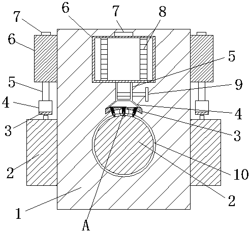
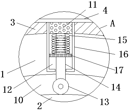
Coaxial reversing box

A reversing box and coaxial technology, which is applied in the field of reversing boxes, can solve the problems of increasing the friction between the rotating shaft and the switching box, the smooth rotation of the rotating shaft, and reducing work efficiency, so as to reduce friction, avoid waste, The effect of improving work efficiency

Inactive Publication Date: 2019-01-01
YANCHENG PUCI MACHINERY CO LTD
View PDF0 Cites 3 Cited by
  • Summary
  • Abstract
  • Description
  • Claims
  • Application Information

AI Technical Summary

Problems solved by technology

[0004] The purpose of the present invention is to solve the shortcomings in the prior art, such as: the existing coaxial reversing box, in the process of use, the rotating shaft on the reversing box will change very much on the surface due to long-term rotation. Dry, which increases the friction between the shaft and the conversion box, resulting in the shaft cannot rotate smoothly, thereby reducing work efficiency

Method used


Image

  • Coaxial reversing box
  • Coaxial reversing box

Examples


Embodiment Construction

[0020] The following will clearly and completely describe the technical solutions in the embodiments of the present invention with reference to the accompanying drawings in the embodiments of the present invention. Obviously, the described embodiments are only some, not all, embodiments of the present invention.

[0021] In describing the present invention, it should be understood that the terms "upper", "lower", "front", "rear", "left", "right", "top", "bottom", "inner", " The orientation or positional relationship indicated by "outside", etc. is based on the orientation or positional relationship shown in the drawings, and is only for the convenience of describing the present invention and simplifying the description, rather than indicating or implying that the referred device or element must have a specific orientation, so as to Specific orientation configurations and operations, therefore, are not to be construed as limitations on the invention.

[0022] refer to Figure ...


PUM


Abstract

The invention discloses a coaxial reversing box. The coaxial reversing box comprises a box body. Rotating cavities are correspondingly formed in the front face and the left and right side walls of thebox body. A rotating shaft is rotationally connected in each rotating cavity. Lubricating devices are correspondingly arranged on the front face and the left and right side walls of the box body. According to the coaxial reversing box, when the box body is connected with a power source to drive the rotating shafts to rotate, valves are turned on to enable lubricating oil in oil tanks to flow intohoppers through oil inlet pipes, and slight vibration occurs to the box body in the rotating process of the rotating shafts, so that the lubricating oil is accelerated to soak into oil absorption sponge faster, and the lubricating oil slowly flows into pulleys along the side walls of guide rods through the oil absorption sponge; and when the rotating shafts drive the pulleys to rotate together, the surfaces of the rotating shafts are uniformly coated with the lubricating oil, so that the surfaces of the rotating shafts are wetter and smoother, the friction force between the rotating shafts and the inner walls of the rotating cavities is reduced, the rotating shafts can rotate more smoothly, and the working efficiency is improved.

Description

technical field [0001] The invention relates to the technical field of reversing boxes, in particular to a coaxial reversing box. Background technique [0002] As an important supporting component of the reducer, the reversing box has a wide range of applications in the current mechanism for power transmission and motion. It is used in almost all kinds of mechanical transmission systems, ranging from vehicles, ships, Automobiles, locomotives, heavy machinery used in construction, processing machinery and automatic production equipment used in the machinery industry, to electric clocks and watches commonly seen in daily life, etc.; [0003] In the existing coaxial reversing box, in the process of use, the rotating shaft on the reversing box will become very dry on the surface due to long-term rotation, thereby increasing the friction between the rotating shaft and the switching box, thereby As a result, the rotating shaft cannot rotate smoothly, thereby reducing work efficie...

Claims


Application Information

Patent Timeline
Patent Type & Authority Applications(China)
IPC IPC(8): F16H57/04
CPCF16H57/0467F16H57/043F16H57/0434F16H57/045
Inventor 高健
Owner YANCHENG PUCI MACHINERY CO LTD
Why Eureka
Try Eureka