
Inertial navigation positioning measurement full-energy gear train system

A technology of inertial navigation and positioning measurement, which is applied in directions such as navigation through speed/acceleration measurement, and can solve problems such as the offset between the gyroscope and the central axis of the pipeline, the attitude change of the inertial navigation locator, and the decrease in measurement accuracy, so as to ensure the measurement Accuracy, increase contact area, reduce wear effect

Pending Publication Date: 2019-01-01
唐山市中宇科技发展有限公司
View PDF0 Cites 1 Cited by
  • Summary
  • Abstract
  • Description
  • Claims
  • Application Information

AI Technical Summary

Problems solved by technology

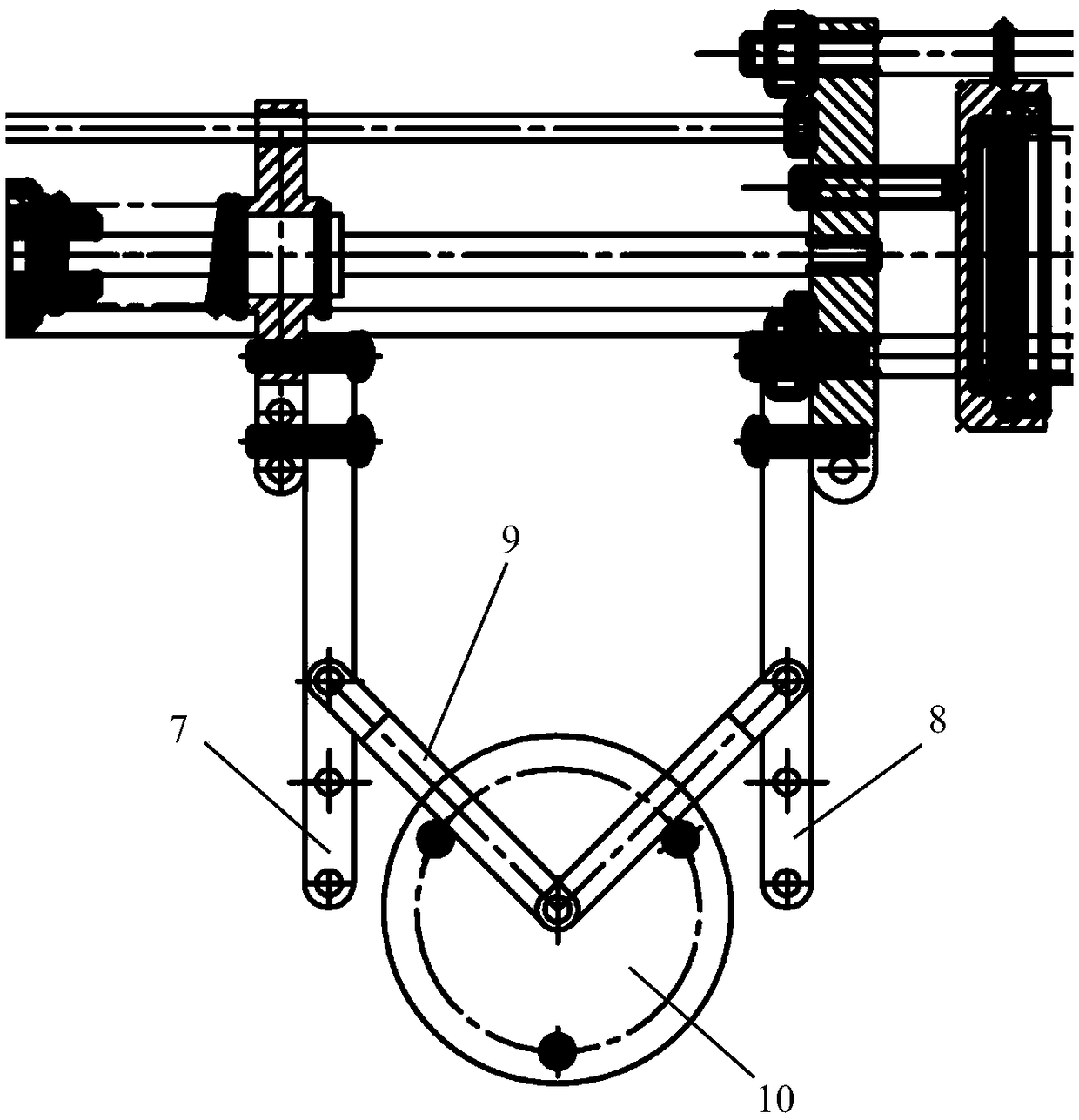
[0013] At present, the gear train system of the existing inertial navigation locator at home and abroad adopts a three-wheel adaptive gear train mechanism. Although it can adapt to the inner diameter of the pipeline during measurement, due to the uncertain factors of adaptive size in the adaptive gear train, if it encounters the inner diameter of the pipeline When foreign objects or pipelines are bent, the gear train will be greatly deformed, causing the attitude of the inertial navigation locator to change, that is, the gyroscope and the central axis of the pipeline will deviate, resulting in a serious drop in measurement accuracy

Method used


Image

  • Inertial navigation positioning measurement full-energy gear train system
  • Inertial navigation positioning measurement full-energy gear train system
  • Inertial navigation positioning measurement full-energy gear train system

Examples


Embodiment Construction

[0037] The following will clearly and completely describe the technical solutions in the embodiments of the present invention with reference to the accompanying drawings in the embodiments of the present invention. Obviously, the described embodiments are only some, not all, embodiments of the present invention. Based on the embodiments of the present invention, all other embodiments obtained by persons of ordinary skill in the art without making creative efforts belong to the protection scope of the present invention.

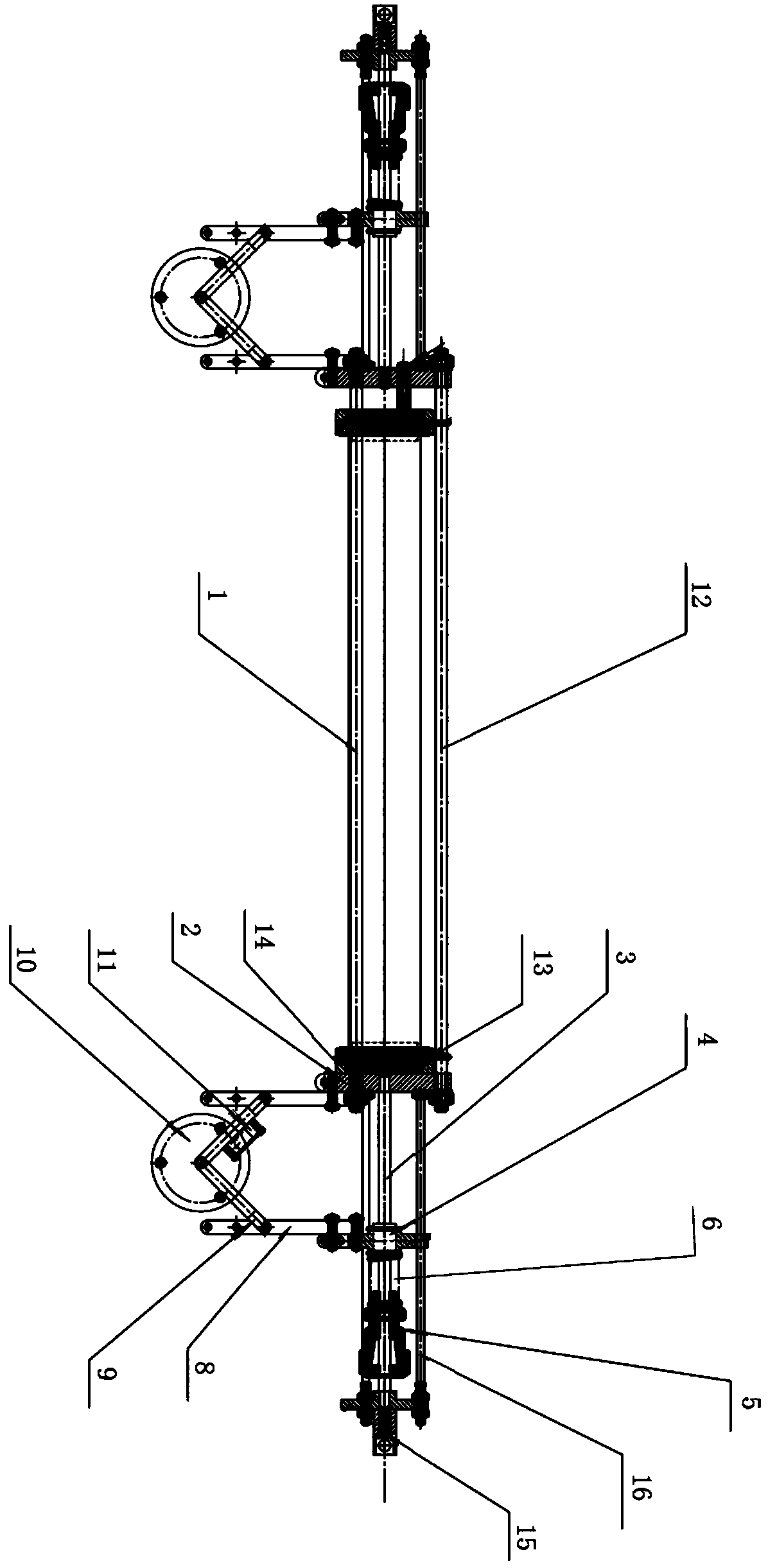
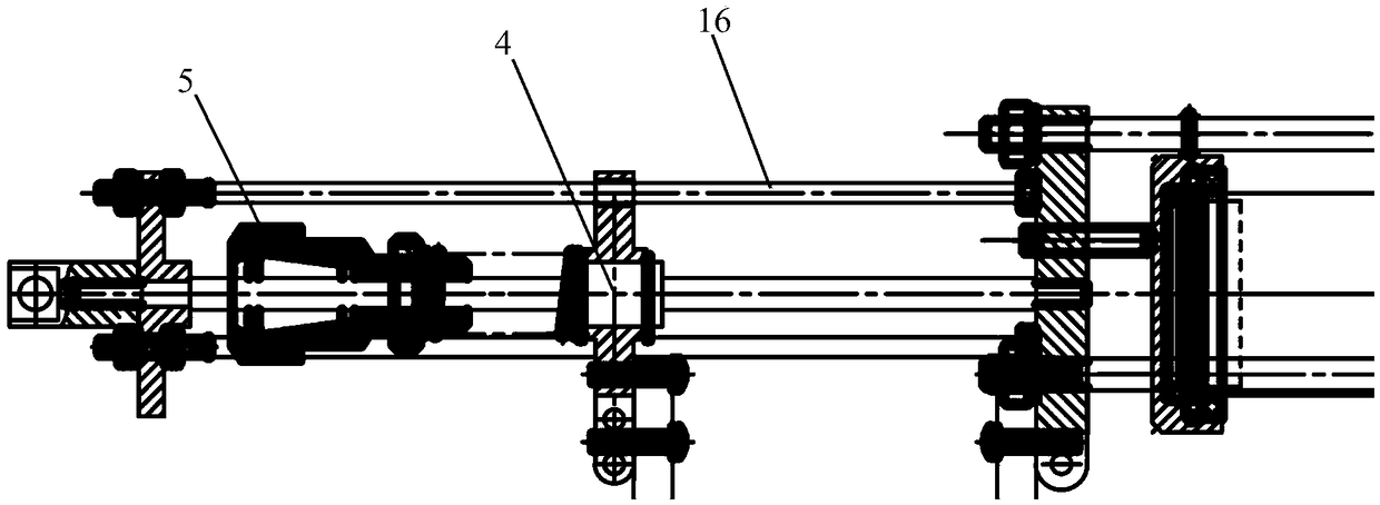
[0038] Referring to the relevant drawings, the present invention discloses an inertial navigation positioning measurement all-round gear train system, including a central rod fine-tuning locking mechanism 5, a multi-diameter series gear train support arm system, an inertial navigation locator suspension shock absorption system, an inertial navigation The locator multi-diameter gear train and support arm series system and the omnipolar Hall switch meter sensor s...


PUM


Abstract

The invention discloses an inertial navigation positioning measurement full-energy gear train system which comprises center rod fine adjustment and deadlocking mechanisms, a multi-pipe diameter serialgear train supporting arm system, an inertial navigation positioning instrument suspension shock absorption system, an inertial navigation positioning instrument multi-pipe diameter gear train and asupporting arm serial system; the inertial navigation positioning instrument suspension shock absorption system is installed at the top end of an inertia instrument rigid skeleton to provide rigid supporting and soft connection when an inertial navigation positioning instrument performs measurement and running; the two ends of the inertia instrument rigid skeleton are provided with bearing straight rails through adapter flanges respectively; each bearing straight rail is provided with a linear bearing; the position, close to the end part, of each bearing straight rail is provided with the corresponding fine adjustment and deadlocking mechanism; and the fine adjustment and deadlocking mechanisms are connected with the linear bearings through fine adjustment springs respectively. By adoptingthe inertial navigation positioning measurement full-energy gear train system provided by the invention, the center rod fine adjustment and deadlocking mechanisms provide the spring pressure, and thespring pressure is converted to the adhesion force of the gear train to the pipe wall and the friction force of a tread to the pipe wall when the gear train advances, so that a gyroscope gear train is ensured not to slip and lose rotation, and the measurement accuracy of an inertial navigation gyroscope is ensured.

Description

technical field [0001] The invention relates to the technical field of navigation and positioning gear trains, in particular to an inertial navigation, positioning and measurement all-round gear train system. Background technique [0002] With the rapid development of modern cities, the underground pipeline network system is increasingly developed, and various pipelines such as electricity, telecommunications, gas, water supply and drainage, rainwater and sewage are densely covered with cobwebs and intricate. However, due to historical and technical reasons, the established underground pipelines seldom provide accurate pipeline location and buried depth, which affects the management and maintenance of the increasingly large pipeline network system. How to accurately detect the location and buried depth of underground pipelines such as power pipelines has become an urgent problem to be solved. Traditional pipeline detection methods mostly use geophysical methods, or use elec...

Claims


Application Information

Patent Timeline
IPC IPC(8): G01C21/18
CPCG01C21/18
Inventor 张俊卿李智刘建芬秦中许军
Owner 唐山市中宇科技发展有限公司
Learn More