Cast-in-place box beam and cross beam multi-layer steel bar installation supporting system device and construction method thereof

A technology of support system and construction method, applied in bridges, bridge construction, erection/assembly of bridges, etc., can solve problems such as difficulty in meeting construction requirements, difficulty in positioning and operation of steel bars, inconvenience for repeated use, etc., and achieve clear force transmission and shortening. The effect of convenient construction period and dismantling

Pending Publication Date: 2022-04-29
CHINA MCC5 GROUP CORP
View PDF0 Cites 2 Cited by
  • Summary
  • Abstract
  • Description
  • Claims
  • Application Information

AI Technical Summary

Problems solved by technology

This traditional support system has the following disadvantages: 1. The use of steel pipes is large, the reinforcement installation is cumbersome and the work efficiency is low; 2. When the operators replace and remove the steel pipe frames, they need to construct in multi-layer steel cages, which is difficult to operate and dangerous. Larger; 3. The steel skeleton is high, and the stability is poor, and the positioning of the steel bars is difficult; 4. It is inconvenient to dismantle and reuse, and it is difficult to meet the actual construction needs on site

Method used


Image

  • Cast-in-place box beam and cross beam multi-layer steel bar installation supporting system device and construction method thereof
  • Cast-in-place box beam and cross beam multi-layer steel bar installation supporting system device and construction method thereof

Examples


Embodiment Construction

[0051] In order to understand the above-mentioned purpose, features and advantages of the present invention more clearly, the present invention will be further described in detail below in conjunction with the accompanying drawings and specific embodiments. It should be noted that, in the case of no conflict, the embodiments of the present application and the features in the embodiments can be combined with each other.

[0052] In the following description, many specific details are set forth in order to fully understand the present invention. However, the present invention can also be implemented in other ways than described here. Therefore, the protection scope of the present invention is not limited by the specific implementation disclosed below. Example limitations.

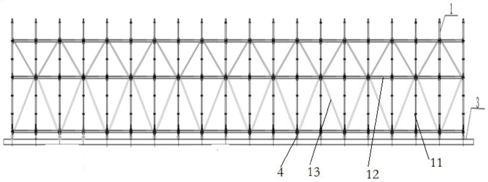
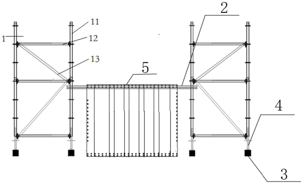
[0053] Refer below Figure 1 to Figure 2 The installation and support system device and construction method of the cast-in-situ box girder beam multi-layer reinforcement provided according to some embodiment...


PUM


Abstract

The invention provides a cast-in-place box beam and cross beam multi-layer steel bar installation supporting system device and a construction method thereof. The cast-in-place box beam and cross beam multi-layer steel bar installation supporting system device comprises a supporting cushion structure. The adjustable bottom support is arranged on the supporting cushion structure; the disc buckle frame body is detachably connected with the adjustable bottom support; and the supporting cross rod is arranged on the disc buckle frame body. The whole device is simple in structure, stable, reliable and high in operability; the construction method is easy to operate, high in speed and remarkable in work efficiency; standardized manufacturing can be conducted, erecting and disassembling are convenient and safe, cyclic utilization is achieved, cost is saved, and the construction period is shortened; the whole device is clear in force transmission, high in bearing capacity and good in stability, effectively solves the problems of temporary supporting and positioning during binding and mounting of multiple layers of reinforcing steel bars of the cast-in-place box girder and the problem of operation of operators in a reinforcing steel bar cage, and greatly guarantees construction safety in the reinforcing steel bar mounting process.

Description

technical field [0001] The invention relates to the technical field of installation of cast-in-place box girder crossbeams, in particular to a support system device and construction method for installing multi-layer steel bars of cast-in-place box girder crossbeams. Background technique [0002] In recent years, with the rapid development of infrastructure, prestressed cast-in-place box girder has become a common design form of bridge construction and has been more and more widely used. Beams are an important stress-bearing structure of cast-in-place box girders, especially for cast-in-place girder bridges with wide decks and only longitudinal prestress. , increase the amount of reinforcement. The steel bar skeleton of the beam is high, the number of steel bars is many, the arrangement is dense, the area is large, and the weight is heavy. The installation speed and stability of the steel bar installation and support system directly affect the installation efficiency of the ...

Claims


Application Information

Patent Timeline
Patent Type & Authority Applications(China)
IPC IPC(8): E01D21/00E01D2/04
CPCE01D21/00E01D2/04
Inventor 邱井东朱先均何冰山宋小飞王茜钟佳琳邓金平
Owner CHINA MCC5 GROUP CORP
Why Eureka
Try Eureka