
Digital frequency meter

A digital frequency meter and frequency technology, applied in the field of digital frequency meter, can solve the problems of narrow frequency measurement range, inability to adapt, large volume, etc., and achieve the effect of improving the frequency measurement range

Inactive Publication Date: 2019-01-01
山东中创软件商用中间件股份有限公司
View PDF8 Cites 0 Cited by
  • Summary
  • Abstract
  • Description
  • Claims
  • Application Information

AI Technical Summary

Problems solved by technology

[0002] In traditional electronic measuring instruments, oscilloscopes have low measurement accuracy and large errors in frequency measurement. Spectrum analyzers can accurately measure frequency and measure the spectrum of the signal under test, but the measurement speed is slow and cannot be quickly tracked and captured in real time. The change of the frequency of the signal under test; and the frequency meter can quickly and accurately capture the change of the frequency of the signal under test, so the frequency meter has a very wide range of applications
[0003] Many functions of the traditional digital frequency meter are realized by a large number of hardware electronic components such as ordinary sequential circuit combinations, which will cause the disadvantage of large size, and it is not suitable for direct measurement of low-frequency signals, and because the electronic components will Mutual interference is unavoidable, and the signal influence between the lines after the volume is reduced cannot be estimated and avoided, which affects the running speed, precision and accuracy of the digital frequency meter measurement, especially the narrow frequency measurement range, which cannot adapt to today's electronic industry development

Method used


Image

  • Digital frequency meter
  • Digital frequency meter
  • Digital frequency meter

Examples


Embodiment Construction

[0037] The following will clearly and completely describe the technical solutions in the embodiments of the present invention with reference to the accompanying drawings in the embodiments of the present invention. Obviously, the described embodiments are only some, not all, embodiments of the present invention. Based on the embodiments of the present invention, all other embodiments obtained by persons of ordinary skill in the art without making creative efforts belong to the protection scope of the present invention.

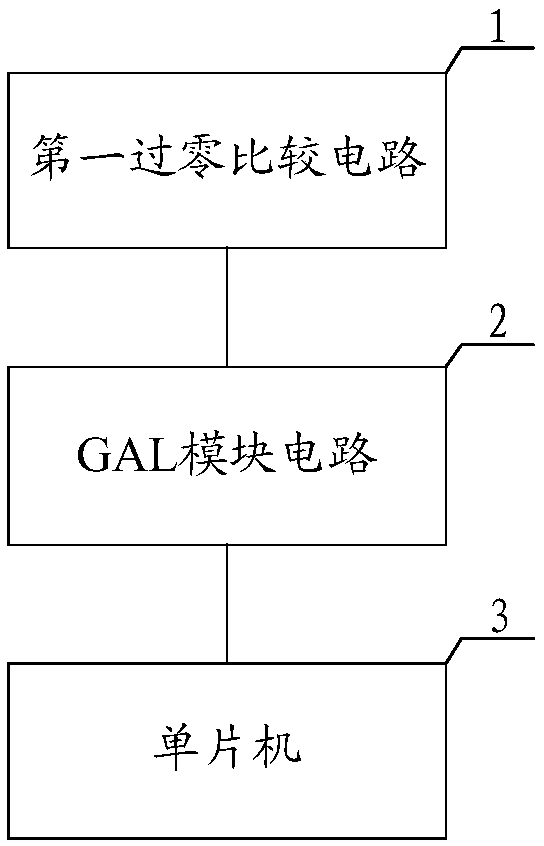
[0038] The embodiment of the present invention discloses a digital frequency meter, see figure 1 As shown, the frequency meter includes: a first zero-crossing comparison circuit 1, a GAL module circuit 2 (GAL, generic array logic, general array logic) and a microcontroller 3 connected in sequence, and the GAL module circuit 2 includes a plurality of cascaded GAL counters ;

[0039] The first zero-crossing comparison circuit 1 is used to convert the input sinu...


PUM


Abstract

The application discloses a digital frequency meter, which includes a first zero-crossing comparison circuit, a GAL (Generic Array Logic) module circuit and a single chip microcomputer connected in sequence. The GAL module circuit includes multiple cascaded GAL counters. The first zero-crossing comparison circuit is used for converting an input sinusoidal signal into a first square wave. The GAL module circuit is used for measuring the frequency of the first square wave sent by the first zero-crossing comparison circuit to obtain a frequency pulse signal. The single chip microcomputer is usedfor getting the frequency of the sinusoidal signal according to the frequency pulse signal. A GAL module circuit including multiple cascaded GAL counters is adopted in the application. The number of output terminals is increased. A pulse signal corresponding to a high-frequency square wave can be output, and the single chip microcomputer can process and calculate the pulse signal accordingly to obtain the frequency of the sinusoidal signal. Frequency measurement of a high-frequency sinusoidal signal is realized, and the range of frequency measurement is increased.

Description

technical field [0001] The invention relates to the field of manufacturing electronic measuring instruments, in particular to a digital frequency meter. Background technique [0002] In traditional electronic measuring instruments, oscilloscopes have low measurement accuracy and large errors in frequency measurement. Spectrum analyzers can accurately measure frequency and measure the spectrum of the signal under test, but the measurement speed is slow and cannot be quickly tracked and captured in real time. The change of the frequency of the signal under test; and the frequency meter can quickly and accurately capture the change of the frequency of the signal under test, so the frequency meter has a very wide range of applications. [0003] Many functions of the traditional digital frequency meter are realized by a large number of hardware electronic components such as ordinary sequential circuit combinations, which will cause the disadvantage of large size, and it is not su...

Claims


Application Information

Patent Timeline
Patent Type & Authority Applications(China)
IPC IPC(8): G01R23/10
CPCG01R23/10
Inventor 单梦娇王蒴高隆林孟庆凯许猛
Owner 山东中创软件商用中间件股份有限公司
Learn More