Method for calculating rotor assembly axis deflection based on end-skip measurement
A technology for rotor assembly and axis deviation, which is applied in the field of rotor assembly axis deviation calculation, and can solve the problems of difficult to ensure the accuracy of axis deviation, difficult to adapt, and parts out of tolerance.
- Summary
- Abstract
- Description
- Claims
- Application Information
AI Technical Summary
Problems solved by technology
Method used
Image
Examples
Embodiment
[0014] A method for calculating the deflection of the rotor assembly axis based on end runout measurement, the steps are as follows:
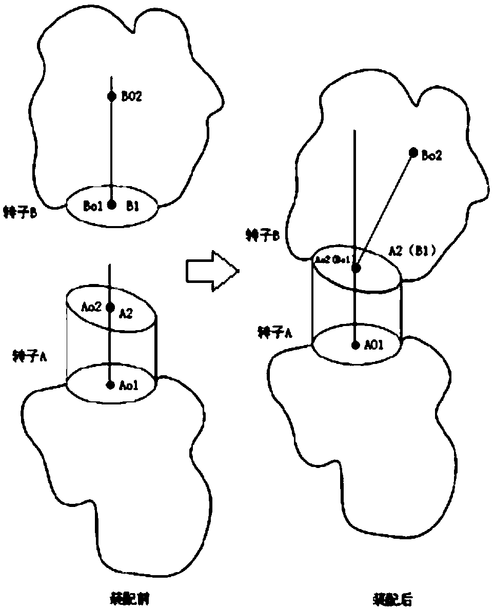
[0015] Step A: Adjacent two-stage discs, the upper and lower centers of rotor A and rotor B are respectively A O2 、A O1 , the upper and lower centers of the rotor B are respectively: B O2 , B O1 , the mating surface of the two rotors is the upper end surface A of rotor A 2 and rotor B lower surface B 1 . Two contact surfaces A 2 , B 1 Represented by a matrix, the form of the data is a ring, respectively A(α,z) and B(α,z), and the jump value z of a certain point at α is represented by polar coordinate representation; the center O of the circle is in the global coordinate system The position of is O(0,0), and the rotor radius R is known; 2 As the base surface, find the lower end surface B of the rotor B 1 in with A 2 Three points in three-point contact, these three points can determine the plane after contact;
[0016] Step B: Calculat...
PUM
 Abstract
Description
Claims
Application Information
 - R&D
- Intellectual Property
- Life Sciences
- Materials
- Tech Scout
- Unparalleled Data Quality
- Higher Quality Content
- 60% Fewer Hallucinations
Browse by: Latest US Patents, China's latest patents, Technical Efficacy Thesaurus, Application Domain, Technology Topic, Popular Technical Reports.
© 2025 PatSnap. All rights reserved.Legal|Privacy policy|Modern Slavery Act Transparency Statement|Sitemap|About US| Contact US: help@patsnap.com


