A method for calculating rotor assembly axis deflection based on end-jump measurement

A rotor assembly and axis deflection technology, which is applied in the field of rotor assembly axis deflection calculation, can solve problems such as difficult adaptation, large errors between the fitting plane and source data, and difficulty in ensuring axis deflection accuracy.

Active Publication Date: 2021-05-07
DALIAN UNIV OF TECH
View PDF5 Cites 0 Cited by
  • Summary
  • Abstract
  • Description
  • Claims
  • Application Information

AI Technical Summary

Problems solved by technology

The fitting plane method is a least squares fitting based on the runout data of the measured rotor end face, and the method of calculating the stacking deflection by fitting the plane equation. This processing algorithm is simple and can grasp the relationship between the two joint surfaces as a whole However, for rotor joint surfaces with "double high points" or irregular topography, the error between the fitting plane and the source data is relatively large, and the accuracy of the predicted axis deflection is difficult to guarantee; the actual rotation centerline method It is the axis deflection prediction method adopted by Axiam Company. Its essence is to find the actual rotation axis generated after assembly by measuring the runout data of the disc end faces at all levels, and adjust and optimize the assembly phase based on this axis. This method is mainly used in foreign countries, and the key technology has not been introduced into China, so it has high prediction accuracy. However, due to the limitation of the manufacturing level of high-end parts in my country, the phenomenon of parts out-of-tolerance is common. There is no basic adjustment of the roundness meter in the application of this method. It is difficult to adapt to the production and assembly process of aero-engine rotors in my country.

Method used


Image

  • A method for calculating rotor assembly axis deflection based on end-jump measurement
  • A method for calculating rotor assembly axis deflection based on end-jump measurement
  • A method for calculating rotor assembly axis deflection based on end-jump measurement

Examples


Embodiment

[0014] A method for calculating the deflection of the rotor assembly axis based on end runout measurement, the steps are as follows:

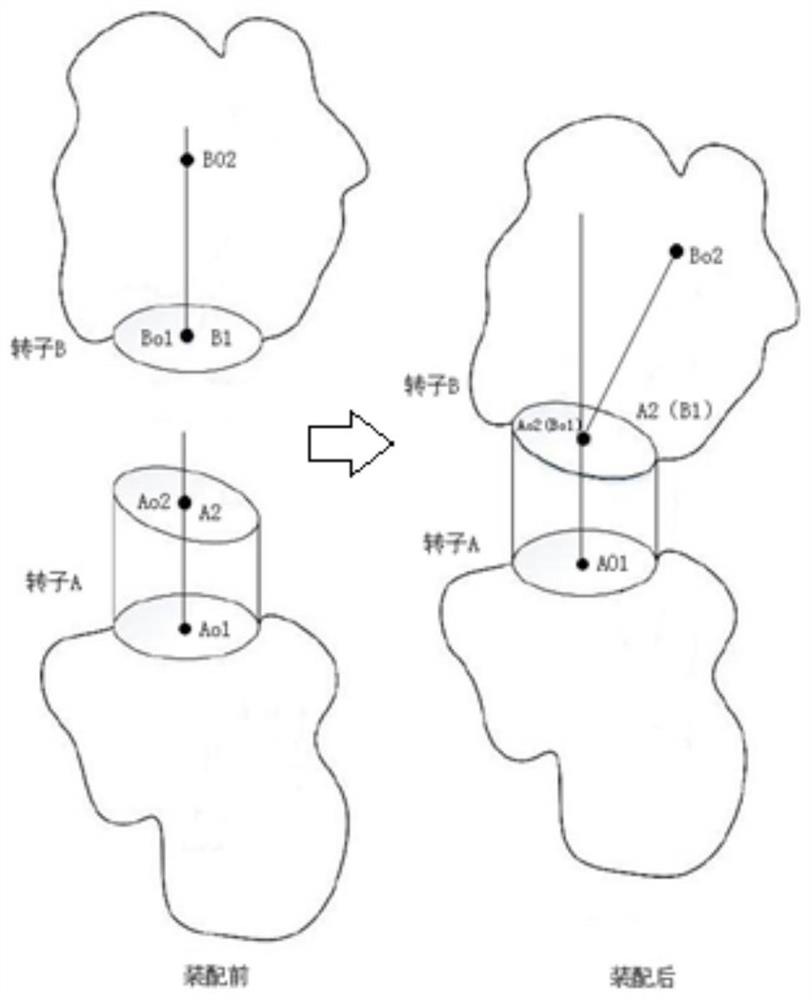
[0015] Step A: Adjacent two-stage discs, the upper and lower centers of rotor A and rotor B are respectively A O2 、A O1 , the upper and lower centers of the rotor B are respectively: B O2 , B O1 , the mating surface of the two rotors is the upper end surface A of rotor A 2 And rotor B lower end surface B 1 . Two contact surfaces A 2 , B 1 Represented by a matrix, the form of the data is a ring, respectively A(α,z) and B(α,z), and the jump value z of a certain point at α is represented by polar coordinate representation; the center O of the circle is in the global coordinate system The position of is O(0,0), and the rotor radius R is known; 2 As the base surface, find the lower end surface B of the rotor B 1 in with A 2 Three points in three-point contact, these three points can determine the plane after contact;

[0016] Step B: Calc...


PUM


Abstract

A method for calculating the deflection of the rotor assembly axis based on end jump measurement, including three parts: the calculation of three contact points, the triangle judgment criterion and the skew matrix homogeneous coordinate transformation algorithm; the three-point contact calculation mainly includes the characterization of the initial measurement data, contact Determination of points, determination of deflection direction and characterization method; the triangle judgment criterion is used to judge whether the obtained three points are in line with reality, and the judgment principle, calculation method and determination process of discarding points are described in detail; the homogeneous coordinate transformation algorithm of skew matrix includes inclination angle Matrix characterization of direction and size, calculation method and matrix representation method of the overall axis deflection of the final assembly result, etc. This method is based on the measured end jump data in actual production, realizes the prediction of the axis deflection before assembly, improves the coaxiality of the rotor after assembly, and greatly improves the pass rate of one-time assembly. The axis prediction, assembly phase adjustment and optimization in the model have important practical guiding significance.

Description

technical field [0001] The invention belongs to a method for calculating the deflection of the rotor assembly axis, which can be applied to the axis prediction, assembly phase optimization, and assembly guidance processes in the assembly process of important components such as aeroengine high-pressure compressor rotors, high-pressure turbine disks, and low-pressure rotor assemblies. Background technique [0002] In the equipment manufacturing process, assembly, as a very important link, has a direct impact on the performance and reliability of the product. For aero-engine rotor components, it is very important to ensure that the coaxiality after assembly meets the requirements. In order to reduce the time and labor costs caused by "trial and error" assembly and improve the coaxiality after assembly, the prediction of assembly phase and Optimization is very important, and in order to improve the pass rate of one-time assembly and reduce the wear and tear of parts and time cos...

Claims


Application Information

Patent Timeline
Patent Type & Authority Patents(China)
IPC IPC(8): G06F17/16
CPCG06F17/16
Inventor 孙清超刘鑫高一超汪云龙
Owner DALIAN UNIV OF TECH
Why Eureka
Try Eureka