Solenoid valve and mass flow controller

A solenoid valve and electromagnetic technology, applied in the direction of flow control, flow control using electric devices, non-electric variable control, etc., can solve the problems of low production efficiency of electromagnetic regulating valves, failure of electromagnetic regulating valves, and inability to achieve sealing, etc., so as to improve once Assembly pass rate, reduce processing difficulty, and reduce processing cost

Active Publication Date: 2022-06-03
BEIJING SEVENSTAR FLOW CO LTD
View PDF5 Cites 0 Cited by
  • Summary
  • Abstract
  • Description
  • Claims
  • Application Information

AI Technical Summary

Problems solved by technology

[0004] However, in the actual installation process, since the spool 13 cannot be guaranteed to be installed in the central position of the inner cavity of the valve body 12, when the coil 11 is energized, the spool 13 will be inclined to attract, causing the spool 13 and the valve port to The through holes 18 of 16 cannot be sealed, which eventually leads to the failure of the electromagnetic regulating valve
In order to ensure that the spool 13 can move vertically as much as possible, it is necessary not only to ensure that the dimensional accuracy of all parts in the electromagnetic control valve is high enough, but also to ensure that the assembly accuracy is high enough, which not only leads to low production efficiency of the electromagnetic control valve. , also lead to a low pass rate of one-time assembly, high scrap rate of parts, etc.

Method used


Image

  • Solenoid valve and mass flow controller
  • Solenoid valve and mass flow controller
  • Solenoid valve and mass flow controller

Examples


Embodiment Construction

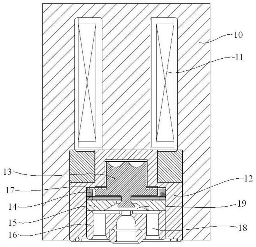
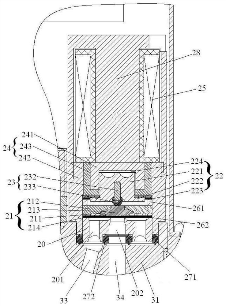
[0035] As shown in FIG. 2 and FIG. 10, the present embodiment provides a solenoid valve 2, including: a solenoid 25, a valve body assembly 24, a valve core

[0036] The solenoid valve 2 provided in this embodiment, because the valve core assembly 22 is in point contact with the plug 211, therefore, in the magnetic seat

[0037] Specifically, as shown in FIG. 2 , the valve core assembly 22, the plug assembly 21, and the valve port component 20 are sequentially stacked on the valve body assembly 24.

[0038] However, in practical applications, the valve core assembly 22, the plug assembly 21, and the valve port component 20 are sequentially stacked on the valve body assembly.

[0041] Optionally, the electromagnetic member 25 can use an electromagnetic coil.

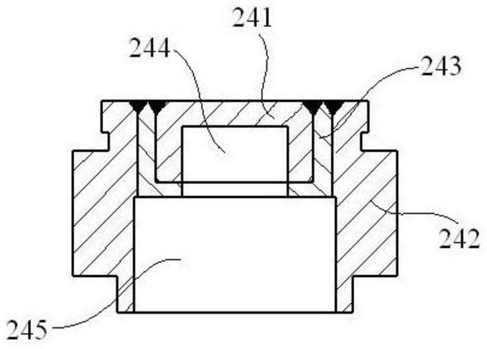
[0045] As shown in FIG. 2 and FIG. 3, in a preferred embodiment of the present invention, the valve body assembly 24 may include a valve body magnetic seat

[0047] Optionally, the valve body magnetic seat 241, the valve body 2...


PUM


Abstract

The invention provides a solenoid valve and a mass flow controller. The solenoid valve includes a solenoid, a valve body assembly, a valve core assembly, a plug assembly, and a valve port component, wherein the valve core assembly, the plug assembly, and the valve port component are stacked in sequence. Placed in the accommodation chamber of the valve body assembly, the valve core assembly is movably arranged in the accommodation chamber, the plug assembly includes a magnetic seat and a plug, the magnetic seat is fixedly arranged in the accommodation chamber, and the plug is movably arranged In the mounting hole of the magnetic seat, the valve core assembly is in point contact with the plug, and the end face of the valve port part facing the plug assembly is provided with a valve port, and the plug is set opposite to the valve port; the electromagnetic part is used to magnetize the valve core assembly and the magnet. seat, so that the magnetic seat attracts the valve core assembly to move, and then drives the plug to move, and adjusts the distance between the plug and the valve port. The electromagnetic valve and the mass flow controller provided by the present invention can improve the working reliability and reduce the difficulty of assembly, so as to improve the first-time assembly pass rate, reduce the processing difficulty of parts and components, reduce the processing cost, and reduce their own volume.

Description

Solenoid valve and mass flow controller technical field [0001] The present invention relates to the technical field of fluid control devices, in particular, to a solenoid valve and a mass flow controller. Background technique [0002] Fluid control devices are widely used in the semiconductor microelectronics industry, photovoltaic industry, special materials, chemical industry, petroleum industry, medical It is widely used in various fields such as medicine, environmental protection and vacuum. Among them, the electromagnetic fluid control device can reduce the pressure, Fluids with high flow are controlled, and have the advantages of better sealing and smaller overall size. [0003] As shown in FIG. 1, the existing electromagnetic regulating valve includes a valve cover 10, a coil 11, a valve body 12, a valve core 13, a gasket 14, and a magnetic seat 15 and valve port piece 16, wherein the coil 11 and the valve body 12 are arranged in the valve cover 10, the valve bod...

Claims


Application Information

Patent Timeline
Patent Type & Authority Patents(China)
IPC IPC(8): F16K31/06F16K1/00G05D7/06
CPCF16K31/0655G05D7/0617
Inventor 苏乾益杜井庆杨宗林
Owner BEIJING SEVENSTAR FLOW CO LTD
Why Eureka
Try Eureka