Supercharge Your Innovation With Domain-Expert AI Agents!

Scintillator

A scintillator and scintillator layer technology, applied in the field of scintillators, can solve the problems of non-airtightness and poor barrier layer, and achieve the effect of thin quality and maintaining performance

Inactive Publication Date: 2019-01-01
流利的波控股有限公司
View PDF11 Cites 1 Cited by
  • Summary
  • Abstract
  • Description
  • Claims
  • Application Information

AI Technical Summary

Problems solved by technology

[0013] Furthermore, prior art barriers are poor at high temperatures and / or highly hygroscopic, especially over time, and are not hermetic, especially when combined with improved optical properties

Method used


Image

  • Scintillator
  • Scintillator
  • Scintillator

Examples


Embodiment Construction

[0038] The invention relates in a first aspect to an improved scintillator for X-rays according to claim 1 .

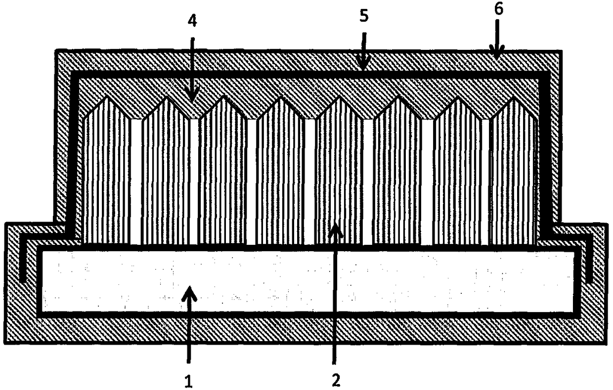
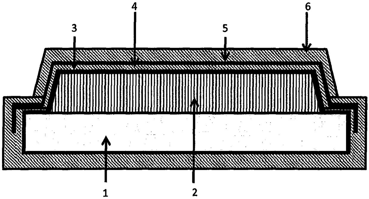
[0039] The scintillator of the present invention includes a substrate layer. In one example, the ply is selected from aluminum, fiber optic and carbon. It should be noted that, as shown in the figure, in the case of a fiber optic plate, the scintillator layer is preferably placed on the plate, while in the case of aluminum and carbon plates, the scintillator is preferably placed below the plate. Aluminum is preferred if relatively high energy x-rays need to be detected, and carbon is preferred when relatively low energy x-rays need to be detected. Carbon also matches well with glass substrates.

[0040] The substrate or plate typically has a thickness of 0.3mm-100mm. In one example, the aluminum plate has a thickness of 0.3mm-1.0mm, the fiber optic plate has a thickness of 1mm-4mm, and the carbon plate has a thickness of 0.5mm-2.0mm. In one example, the plate prot...


PUM


Abstract

The present invention is in the field of an improved scintillator for X-rays, use of the inventive scintillator, an X-ray detector comprising the present scintillator, and a method of producing an improved scintillator. A scintillator converts X-rays into visible light; high performance scintillators are typically made of a crystalline material.

Description

field of invention [0001] The present invention belongs to the field of scintillators. Background of the invention [0002] A scintillator converts X-rays into visible light. High performance scintillators can be made from crystalline materials such as CsI. Light can be detected by sensors including, for example, diode arrays, photographic plates, and charge-coupled device (CCD) plates. The resulting image is called a radiograph. [0003] In scintillators, two main performance parameters are usually considered, namely light output performance and modulation transfer function. [0004] The modulation transfer function (MTF) is the spatial frequency response of an imaging system or component. It is the contrast at a given spatial frequency relative to low frequencies. MTF is preferably as high as possible. [0005] On radiographs, objects of different sizes and opacities are displayed using different grayscale values. The MTF is responsible for converting the contrast v...

Claims


Application Information

Patent Timeline
Patent Type & Authority Applications(China)
IPC IPC(8): G01T1/202
CPCG01T1/202H01L27/14663H10K39/36G01T1/2002G21K2004/10G21K2004/12
Inventor E·吉利森E·雅各布斯N·多甘
Owner 流利的波控股有限公司
Features
  • R&D
  • Intellectual Property
  • Life Sciences
  • Materials
  • Tech Scout
  • Unparalleled Data Quality
  • Higher Quality Content
  • 60% Fewer Hallucinations
Learn More