[0012] In an alternative specific embodiment, the present invention provides an alternative method for manufacturing devices on multi-layered substrates. The method includes providing a donor substrate, which has a first deflection characteristic. Preferably, the donor substrate has a backside, a face, a cleave region, and a thickness of material defined between the cleave region and the face. The method includes
coupling a backing substrate to the backside of the donor substrate to form a multilayered structure. In a preferred embodiment, the backing substrate is adequate to cause the first deflection characteristic of the donor substrate to be reduced to a predetermined level. The predetermined level is a suitable deflection characteristic for the thickness of material to be transferred onto a face of a
handle substrate while the backing substrate remains attached to the donor substrate to maintain at least the suitable deflection characteristic. The method includes bonding the face of the donor substrate to a face of the handle substrate. The method includes initiating a controlled cleaving process within a portion of the cleave region of the donor substrate to begin removal of the thickness of material from the donor substrate at a portion of the cleave region and continues to free the thickness of material from the donor substrate. Preferably, one or more devices is fabricated onto portions of the thickness of material.
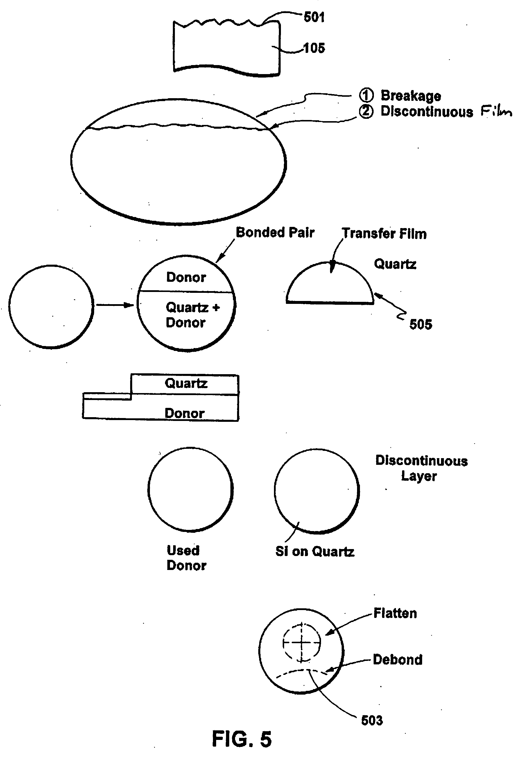
[0015] Still further, the present invention provides a method for manufacturing devices on multi-layered substrates comprising transparent materials, e.g., glass,
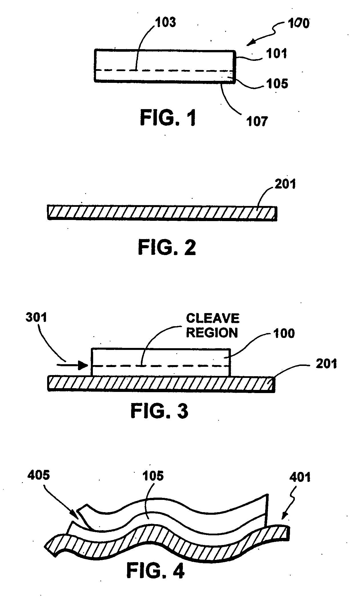
quartz. The method includes providing a transparent handle substrate, which has a first deflection characteristic. The transparent handle substrate has a backside and a face. The method includes initiating engagement of a backing substrate to the backside of the transparent handle substrate and attaching the backing substrate to the backside of the transparent handle substrate to firmly engage the backing substrate to the transparent handle substrate to form a multilayered structure. Preferably, the backing substrate is adequate to provide an effective deflection characteristic of the multilayered structure to be suitable for a thickness of
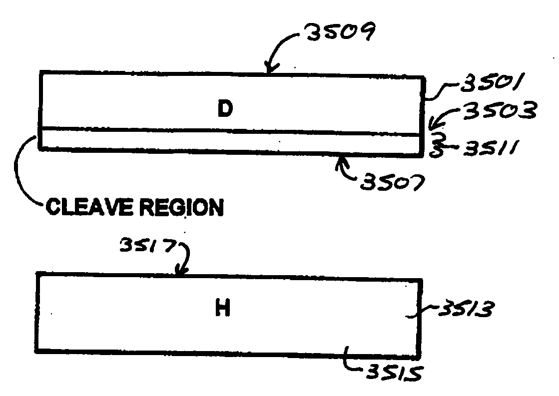
silicon bearing material to be transferred onto the face of the handle substrate. The method includes providing a donor substrate comprising a cleave region, the thickness of material, and a surface region. The cleave region is within the donor substrate to define the thickness of
silicon bearing material, which is provided between the cleave region and the surface region. The method includes bonding the surface region of the donor substrate to the face of the transparent handle substrate, while the backing substrate remains attached to the handle substrate to substantially maintain the effective deflection characteristic. The method initiates a controlled cleaving process within a portion of the cleave region of the donor substrate to begin removal of the thickness of
silicon bearing material from the donor substrate at a portion of the cleave region and continues to free the thickness of material from the donor substrate. Preferably, one or more devices is fabricated onto portions of the thickness of material.
[0022] Numerous benefits are achieved over pre-existing techniques using the present invention. In particular, the present invention uses controlled energy and selected conditions to preferentially cleave a thin film of material from a donor substrate which includes multi-material sandwiched films. This cleaving process selectively removes the thin film of material from the substrate while preventing a possibility of damage to the film or a remaining portion of the substrate. Accordingly, the remaining substrate portion can be re-used repeatedly for other applications. Additionally, the present invention uses a relatively low temperature during the controlled cleaving process of the thin film to reduce temperature excursions of the separated film, donor substrate, or multi-material films according to other embodiments. This lower temperature approach allows for more material and process
latitude such as, for example, cleaving and bonding of materials having substantially different
thermal expansion coefficients. In other embodiments, the present invention limits energy or stress in the substrate to a value below a cleave
initiation energy, which generally removes a possibility of creating random cleave
initiation sites or fronts. This reduces cleave damage (e.g., pits, crystalline defects, breakage, cracks, steps, voids, excessive roughness) often caused in pre-existing techniques. Moreover, the present invention reduces damage caused by higher than necessary stress or pressure effects and
nucleation sites caused by the energetic particles as compared to pre-existing techniques. Preferably, the
present method and structure provides a backing structure that allows for cleaving onto substrates, which cannot effectively receive transferred films. Such backing substrate provides a certain stiffness to either or both substrates, including donor and handle, to allow effective cleaving onto thin flexible substrates according to specific embodiments. In preferred embodiments, the present invention provides a method and structure that forms a
thin layer of material transferred onto a flexible substrate, without any major back
grinding and / or
thinning operations on the flexible substrate. Depending upon the embodiment, one or more of these benefits may be achieved. These and other benefits may be described throughout the present specification and more particularly below.

