British standard plug of novel riveting mode

A new type of riveting technology, applied in the direction of connection, electrical components, circuits, etc., can solve problems such as falling off, terminal pieces cannot be tightly pressed and connected, and it is difficult to ensure uniform deformation and expansion of riveted parts, so as to avoid loosening up and down, improve conductive stability, The effect of simple production process

Inactive Publication Date: 2019-01-04
广东顺德安电电器实业有限公司
View PDF9 Cites 0 Cited by
  • Summary
  • Abstract
  • Description
  • Claims
  • Application Information

AI Technical Summary

Problems solved by technology

[0002] During the processing of the plug, it is necessary to install the electric pin on the inner frame first, then install the terminal piece on the riveted part of the electric pin, and then press the riveted part flattened by the punching device, so that the flat riveted part and the terminal piece are tightly connected , but in the stamping process of this stamping method, it is difficult to ensure that the riveting part deforms and expands uniformly in the circumferential direction when it is pressed, which causes the problem that the connection structure between the riveting part and the terminal piece is unstable, and may even fall off. Therefore, some of the riveting parts today The riveting method adopts the spin riveting method, but during the spin riveting process, the spin riveting head will only exert pressure on the top surface of the riveting part, so that the riveting part expands outwards evenly in the shape of a mushroom, but the disadvantage of spin riveting is that in the spin riveting Finally, the bottom surface of the riveted part cannot be pressed tightly on the terminal piece, and there is a gap between the terminal piece and the terminal piece, or the terminal piece and the inner frame cannot be tightly connected, leaving a gap, resulting in the failure of conductive connection, etc., causing the plug to fail to meet the requirements. safety standard

Method used


Image

  • British standard plug of novel riveting mode
  • British standard plug of novel riveting mode
  • British standard plug of novel riveting mode

Examples


Embodiment Construction

[0024] The present invention will be further described below in conjunction with the accompanying drawings and embodiments.

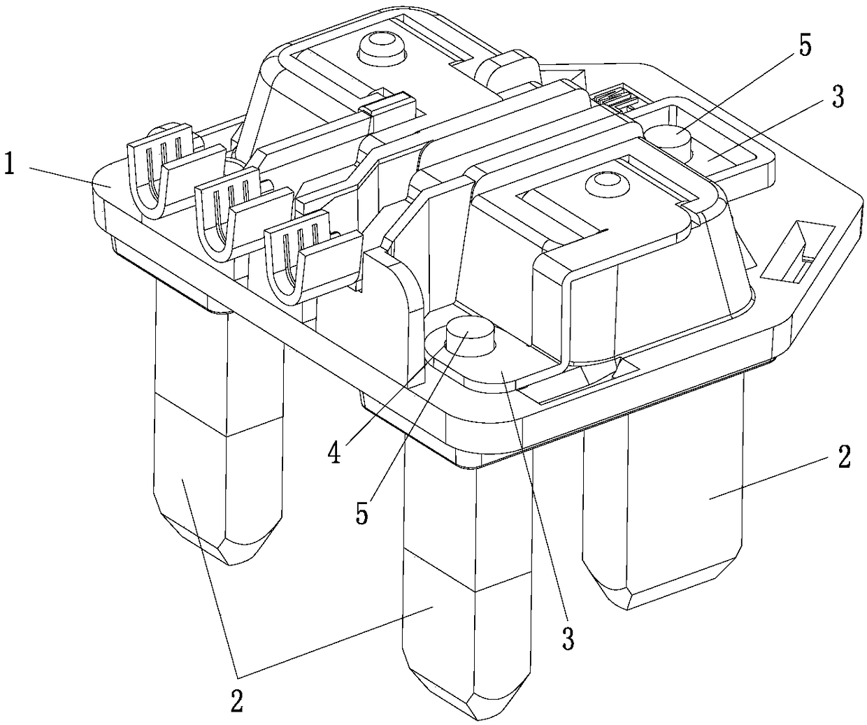
[0025] Such as figure 1 As shown, a new type of riveted British standard plug includes an inner frame 1, an electrical pin 2 is connected to the inner frame 1, each electrical pin 2 is electrically connected to a terminal piece 3, and a connecting hole is provided on the terminal piece 3 4. The electric pin 2 is provided with a riveting part 5 inserted into the connection hole 4, and the steps are as follows:

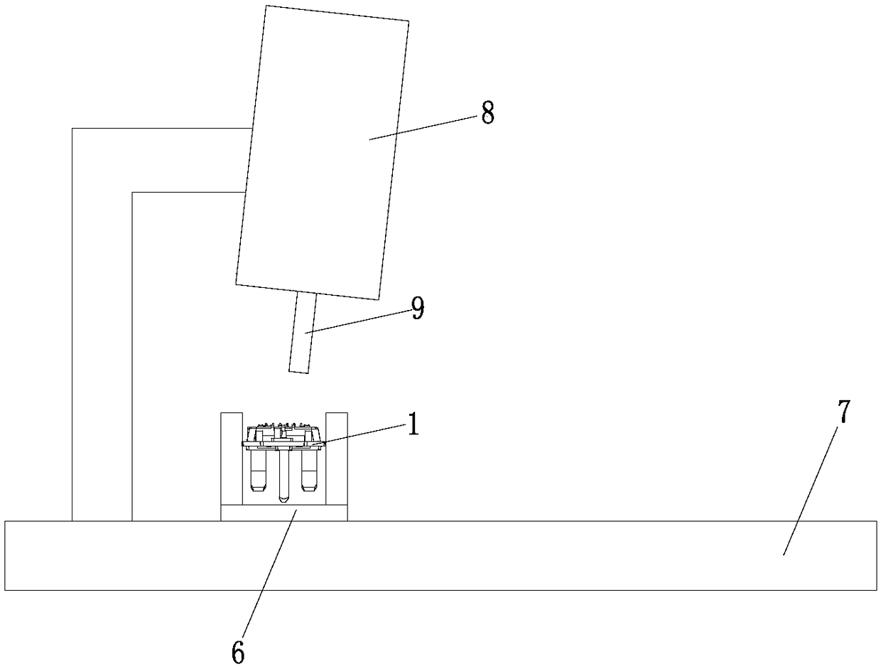
[0026] One, such as Figure 2 to Figure 3 As shown, the inner frame 1 is installed on the first workbench 7 provided with the riveting jig 6, the riveting device 8 is arranged above the riveting jig 6, and the riveting head 9 at the bottom of the riveting device 8 is pressed against the riveting part 5 top; it can fix the inner frame 1 to prevent the inner frame 1 from shifting during processing.

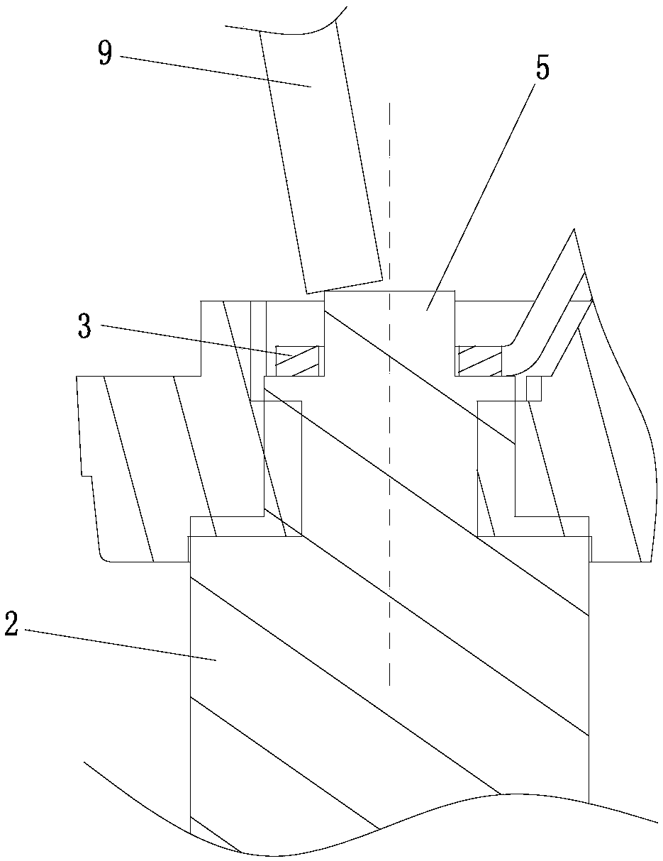
[0027] Two, if Figure 4 As shown, the spin ...


PUM


Abstract

A British standard plug of a novel riveting mode comprises an inner frame connected with electric plug pins. Each electric plug pin is electrically connected with a terminal piece provided with a connecting hole. The electric plug pins are provided with riveting parts inserted into the connecting holes. Rotary riveting pressing heads of rotary riveting devices do rotation motion around the centeraxes of the riveting parts and conduct downward feeding, so that the rotary riveting pressing heads press and abut against the top faces of the riveting parts, the top face temperature of the rivetingparts are increased through heat generated by friction between the rotary riveting pressing heads and the riveting parts, hardness is lowered, the periphery outer end faces of the riveting parts expand outwards evenly in a mushroom shape under the action of downward pressure of the rotary riveting pressing heads, and rotary riveting is completed. A stamping head of a stamping device fast stamps to the tops of the riveting parts, thus the bottom faces of the flattened riveting parts tightly press the terminal pieces, and the bottom faces of the terminal pieces tightly press the inner frame. Through the structure, the riveting parts can expand outwards evenly and can tightly press the terminal pieces, and stability of the electric connection structure is improved.

Description

technical field [0001] The invention relates to the field of ultra-thin British standard plugs, in particular to a novel riveted British standard plug. Background technique [0002] During the processing of the plug, it is necessary to install the electric pin on the inner frame first, then install the terminal piece on the riveted part of the electric pin, and then press the riveted part flattened by the punching device, so that the flat riveted part and the terminal piece are tightly connected , but in the stamping process of this stamping method, it is difficult to ensure that the riveting part deforms and expands uniformly in the circumferential direction when it is pressed, which causes the problem that the connection structure between the riveting part and the terminal piece is unstable, and may even fall off. Therefore, some of the riveting parts today The riveting method adopts the spin riveting method, but during the spin riveting process, the spin riveting head wil...

Claims


Application Information

Patent Timeline
IPC IPC(8): B21J15/12B21D39/00H01R43/00
CPCB21D39/00B21J15/12H01R43/00
Inventor 麦建敏
Owner 广东顺德安电电器实业有限公司
Why Eureka
Try Eureka