
Forming die for piston valve plate

A technology for forming molds and piston valves, which is used in casting molding equipment, cores, and casting molds, etc., can solve the problems of piston valve valve sheet size not meeting production requirements, unfavorable cooling and heat dissipation of castings, and reducing product qualification rate. Conducive to heat dissipation and rapid cooling, reducing product qualification rate, not easy to loosen and collapse

Active Publication Date: 2019-01-04
山西安信铸造科技股份有限公司
View PDF9 Cites 3 Cited by
  • Summary
  • Abstract
  • Description
  • Claims
  • Application Information

AI Technical Summary

Problems solved by technology

At present, the upper and lower parting surfaces of the sand box are used to cast the piston valve valve plate. When the sand box is filled with molding sand to form a mold cavity, the sand box used is a cubic box structure, and the inner wall of the sand box is vertical. Face to face, in the process of casting the mold, the molding sand is easy to slide between the inner wall of the sand box, causing the mold cavity to loosen and fall off, and then the size and specification of the cast piston valve valve plate do not meet the production requirements, reducing the product qualification rate
In addition, a large amount of molding sand needs to be filled, which increases the production cost and makes the thickness of the local molding sand thicker, which is not conducive to the cooling and heat dissipation of the casting

Method used


Image

  • Forming die for piston valve plate
  • Forming die for piston valve plate
  • Forming die for piston valve plate

Examples


Embodiment

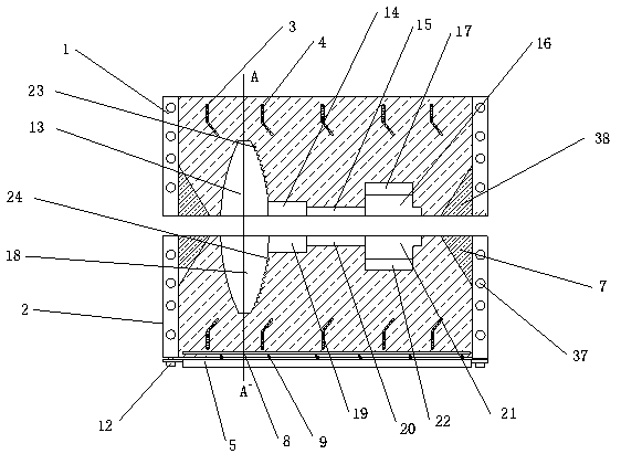
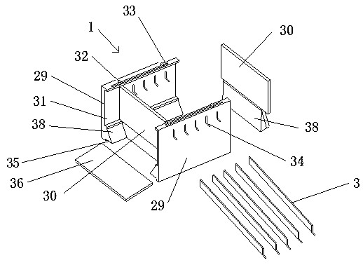
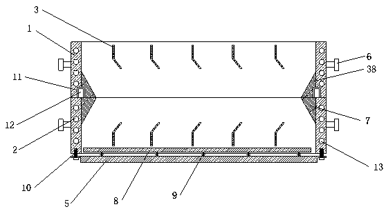
[0028] Embodiment: a kind of piston valve valve plate molding die, as attached Figure 1-5 As shown, it includes an upper sand box 1 and a lower sand box 2; the upper sand box 1 and the lower sand box 2 are both internally hollow and the upper and lower bottom surfaces are open box structures, and the upper sand box 1 and the lower sand box are open. The side walls of the lower flask 2 are provided with second cooling passages 37 to facilitate cooling of the molding sand, thereby increasing the cooling rate of the casting. The upper end of the inner cavity of the upper sand box 1 and the lower end of the inner cavity of the lower sand box 2 are respectively provided with a plurality of curved partition plates 3, and each partition plate 3 is provided with a plurality of first and second walls that run through the two ends of the partition plate 3. A cooling passage 4; the partition plate 3 includes a base plate, and the end of the base plate is provided with a bent plate; the ...


PUM


Abstract

The invention discloses a forming die for a piston valve plate. The forming die comprises an upper sand box and a lower sand box, wherein each of the upper sand box and the lower box is of a box structure with hollow inside and open upper and lower bottom surfaces, a plurality of bent partition plates are arranged at the upper end of the inner cavity of the upper sand box and the lower end of theinner cavity of the lower sand box respectively, and a plurality of first cooling channels penetrating through two ends of the partition plates are formed in each partition plate; first extension blocks extending inwards are arranged on the inner wall of the upper end of the lower sand box, a base is fixed at the bottom of the lower sand box through bolts, a bottom plate is arranged above the base, and a plurality of compression springs are arranged between the bottom plate and the base; an upper cavity with semicircular section and arc-shaped side wall is formed in the upper sand box; a lowermold cavity matched with the upper mold cavity is formed in the lower sand box. The forming die can effectively prevent molding sand in the sand boxes from loosening and falling off, stability of thesand boxes is improved, and accordingly, casting quality of products is greatly improved; besides, the use amount of the molding sand is reduced, the production cost is reduced, and the cooling effect is good.

Description

technical field [0001] The invention relates to a valve plate of a piston valve, in particular to a mold for forming a valve plate of a piston valve. Background technique [0002] Piston valves are widely used in production and life because of their advantages such as strong sealing, small space occupation, and good water pressure resistance. At present, the upper and lower parting surfaces of the sand box are used to cast the piston valve valve plate. When the sand box is filled with molding sand to form a mold cavity, the sand box used is a cubic box structure, and the inner wall of the sand box is vertical. Face to face, in the process of casting the mold, the molding sand is easy to slide between the inner wall of the sand box, causing the mold cavity to loosen and fall off, and then the size and specification of the cast piston valve valve plate do not meet the production requirements, reducing the product qualification rate . In addition, a large amount of molding sa...

Claims


Application Information

Patent Timeline
Patent Type & Authority Applications(China)
IPC IPC(8): B22C9/22B22C9/02B22C21/14B22C21/12
CPCB22C9/02B22C9/22B22C21/12B22C21/14
Inventor 王文安徐湖鹏
Owner 山西安信铸造科技股份有限公司
Learn More