Engine outer duct casing welding device and method

A welding device and engine technology, applied in auxiliary devices, welding equipment, auxiliary welding equipment, etc., can solve the problems of poor welding back protection effect, extremely poor welding seam protection, loss of shielding gas, etc., and achieve uniform protection effect. Reduce welding deformation and ensure the effect of concentricity

Inactive Publication Date: 2019-01-04
AECC AERO SCI & TECH CO LTD
View PDF5 Cites 17 Cited by
  • Summary
  • Abstract
  • Description
  • Claims
  • Application Information

AI Technical Summary

Problems solved by technology

During the trial production, the installation side 2 and the large end of the cylinder were welded first (weld 2), and then the installation side 1 (weld 1) was welded. However, due to the large welding deformation of titanium alloy thin-walled parts, and the problem of secondary clamping, Cannot meet the concentricity requirements of installation side 1 and installation side 2
Observing the reverse weld seam after welding, it is found that the weld seam protection is extremely poor and cannot meet the technical requirements of the weld seam
[0003] Generally, in order to reduce the size of the split expansion block and remove the parts, there is a gap between the expansion blocks when the expansion block expands to the working position, and the protective gas loss in the gap results in poor protection effect on the back of the weld seam.

Method used


Image

  • Engine outer duct casing welding device and method
  • Engine outer duct casing welding device and method
  • Engine outer duct casing welding device and method

Examples


specific Embodiment 1

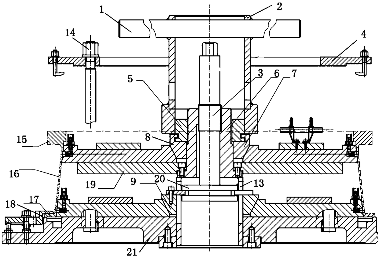
[0032] Such as figure 2 As shown, the present invention includes a base 21, an upper lamination ring 4, a middle expansion ring, a support plate 19, a lower expansion ring, and a moving device.

[0033] From top to bottom along the vertical direction are the upper lamination ring 4 , the middle expansion ring, the support plate 19 , the lower expansion ring, and the base 21 .

[0034] The functions of each part are:

[0035] The base 21 is used to provide support for the present invention.

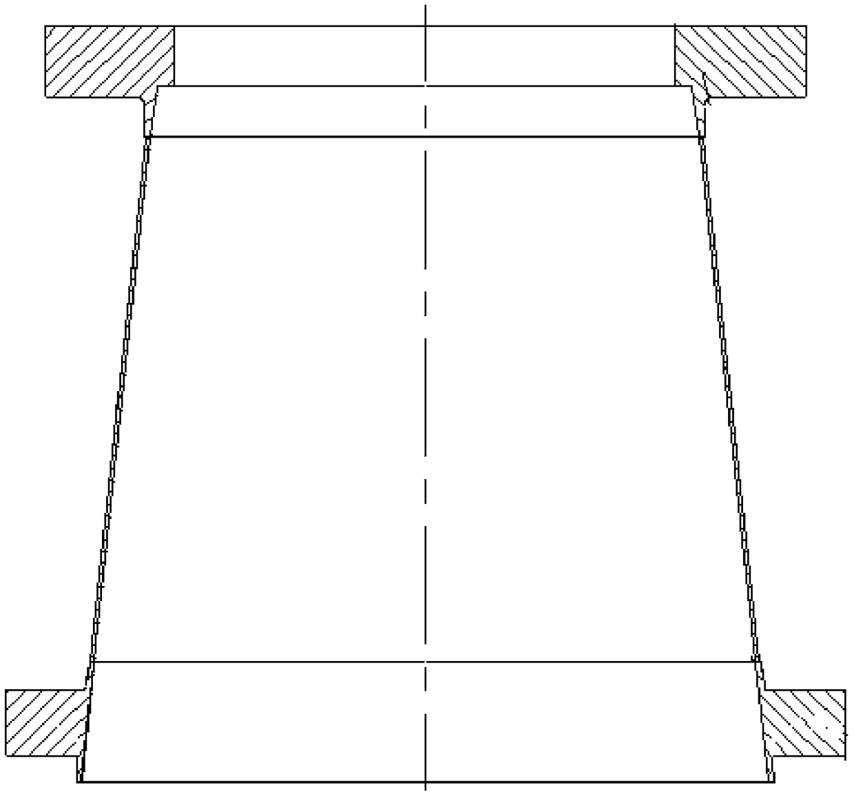
[0036] The upper lamination ring 4 is used to apply downward pressure to the outer duct gate of the engine to be welded.

[0037] The middle expansion ring and the lower expansion ring are used to shape the outer duct gate of the engine to be welded to facilitate welding.

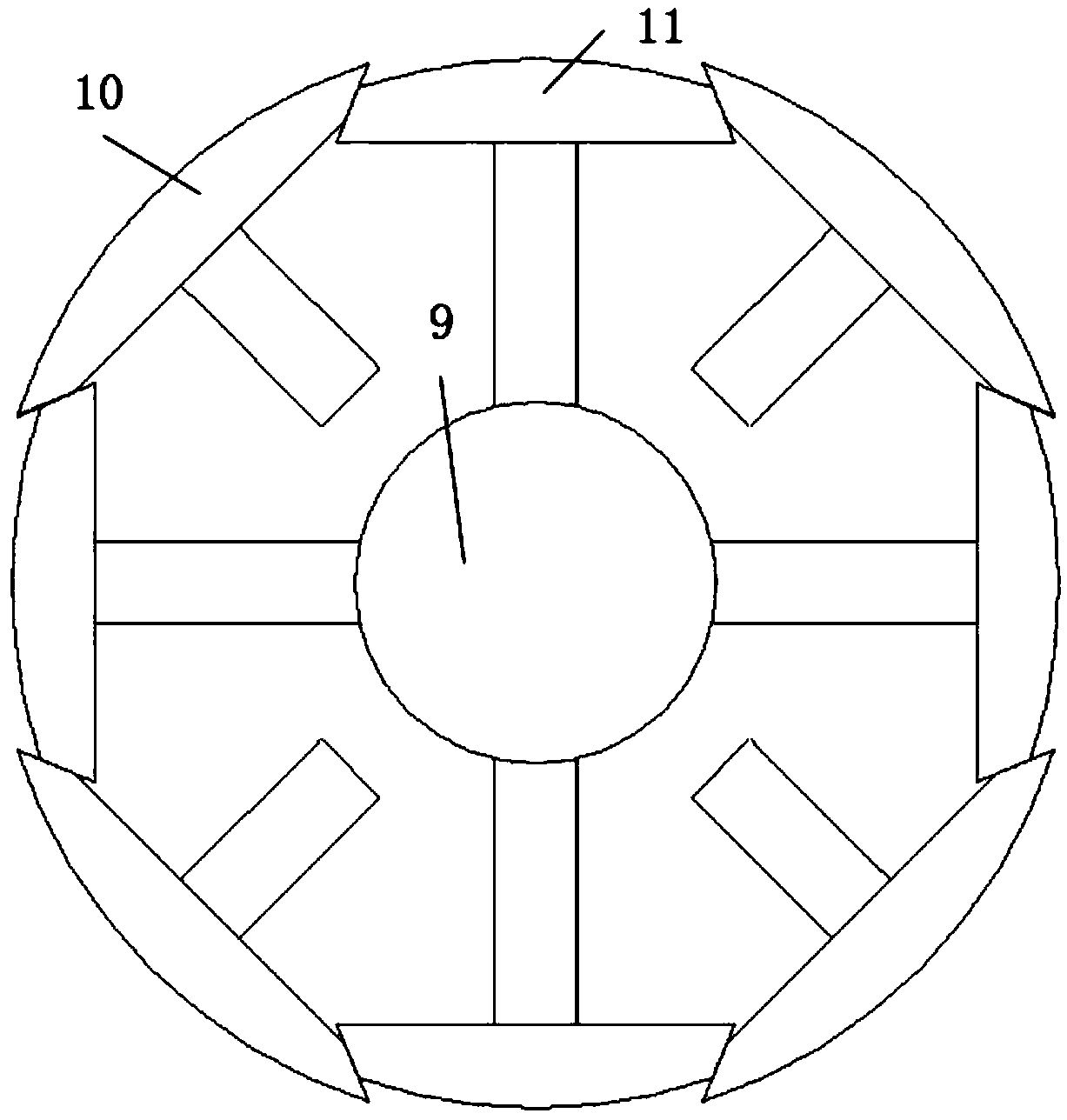
[0038] The moving device is used to control the movement of the middle expansion ring and the lower expansion ring in the direction of the circumferential surface, so that the corresponding part of the outer duct ga...

specific Embodiment 2

[0055] In this embodiment, on the basis of Embodiment 1, the preferred fixing method of the nut 5 and the upper wedge 8 is described.

[0056] The outer lower part of the nut 5 is provided with a groove along the circumferential direction, and a protruding strip matching the shape of the groove is provided on the upper part of the upper wedge 8, and the protruding strip is snapped into the groove so that the nut 5 can drive The upper wedges 8 move together.

specific Embodiment approach 3

[0057] This embodiment is carried out on the basis of embodiment 1 or 2.

[0058] In order to better fix the outer duct gate of the engine to be welded, the outer duct gate of the engine to be welded will not slide during the welding process. The base 21 is provided with a boss around the lower expansion ring, and the cross-section of the boss is L-shaped. It should be understood that the opening direction of the boss is inward.


PUM


Abstract

The invention provides an engine outer duct casing welding device and method. The device comprises a base, an upper-layer pressing ring, a middle-layer expansion ring, a supporting plate, a lower-layer expansion ring and a movement device. Welding deformation is reduced by adopting the sectioning expansion structure, and the overall concentricity of a to-be-welded workpiece is ensured. The sectioning expansion structure is mainly composed of a wedge block, a supporting plate, a driving block, a driven block and the like. In the expansion process, the wedge block is moved downwards, therefore,the driving block is moved outwards, and the driven block is driven till being in tight fit with the part.

Description

technical field [0001] The invention belongs to the technical field of engine equipment tooling, and in particular relates to a welding device and a welding method for an engine outer duct casing. Background technique [0002] The first section of the engine duct casing (such as figure 1 shown) consists of 2 mounting sides and 1 barrel. During the trial production, the installation side 2 and the large end of the cylinder were welded first (weld 2), and then the installation side 1 (weld 1) was welded. However, due to the large welding deformation of titanium alloy thin-walled parts, and the problem of secondary clamping, The concentricity requirements of installation side 1 and installation side 2 cannot be met. Observing the reverse weld after welding, it was found that the protection of the weld was extremely poor and could not meet the technical requirements of the weld. [0003] Generally, in order to reduce the size of the split expansion block and remove the parts,...

Claims


Application Information

Patent Timeline
Patent Type & Authority Applications(China)
IPC IPC(8): B23K37/04
CPCB23K37/0426
Inventor 曾浩
Owner AECC AERO SCI & TECH CO LTD
Why Eureka
Try Eureka