A Pneumatic Supporting Disaster Rescue Robot
What is Al technical title?
Al technical title is built by PatSnap Al team. It summarizes the technical point description of the patent document.
A robot and jacking technology, which is applied in the field of disaster relief robots, can solve the problems of low jacking height and inability to place airbags, and achieve the effect of enlarged entrance, small shape and light weight
Active Publication Date: 2021-05-18
DALIAN UNIV OF TECH
View PDF16 Cites 0 Cited by
Summary
Abstract
Description
Claims
Application Information
AI Technical Summary
This helps you quickly interpret patents by identifying the three key elements:
Problems solved by technology
Method used
Benefits of technology
Problems solved by technology
However, the jacking height of this inflatable airbag is not high, and the inflatable airbag needs to be placed under the collapsed building structure by the disaster relief personnel. This operation is very dangerous, and the airbag cannot be placed in a place where the disaster relief personnel cannot reach. have great limitations
Method used
Image
Click on the blue label to locate the original text in one second.
Reading with bidirectional positioning of images and text.
Examples
Embodiment Construction
[0019]DETAILED DESCRIPTION OF THE PREFERRED EMBODIMENTS
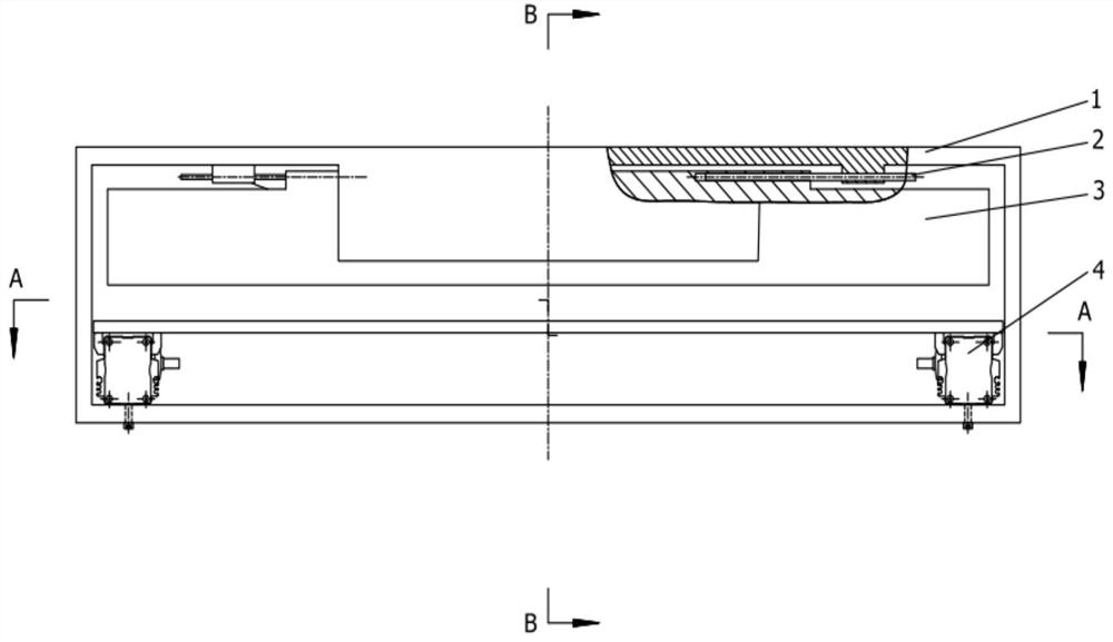
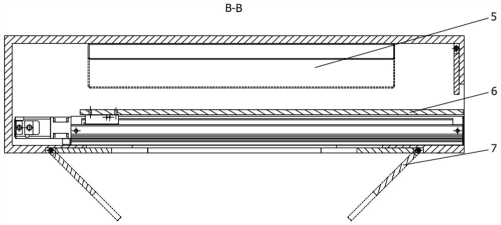
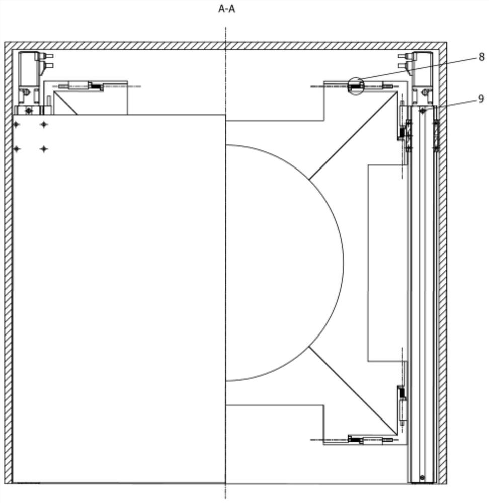
[0020]Pneumatic top-up disaster relief robots can be divided into two parts of the transfer unit and the top rising unit according to the function classification. The transfer unit can be divided into electric slide 4 and slide 6 according to the structure; the tapered unit can be divided into body 1, the pin shaft 2, the side panel 3, the columnar airbag 5, and flip the bottom plate 7. The main body 1 is a main body portion of the search and rescue, the shape is a long square cavity, and the upper portion is used to withstand the weight; the internal cavity mounts the electric slide station 4, the columnar airbag 5, placed the slide 6, the top of the balloon 10; The bottom is provided with a hollow circle, used to pass through the apex, a top having an opening, and is provided by the top-rising air bag 10, and the opening inside is hinged by the pin shaft 2 side panel 3. .
[0021]Transfer processFigure 5 As shown, the pneumatic t...
PUM
Abstract
A pneumatic jacking disaster relief robot belongs to the field of disaster relief robots, comprising an electric slide table, a slide plate, a main body, a side plate, a columnar air bag, a flipping bottom plate, a torsion spring, and a jacking air bag. The main body is a cuboid cavity structure, with a hollow circle in the center of the bottom, which is used to pass the inflated jacking air bag; there is an opening on the side, which is used to pass the uninflated jacking air bag, and the side plate is hinged on the inner side of the opening, and the side plate is stressed Turn only towards the body cavity. Two electric sliding tables are fixed on the bottom of the main body, and the slide plate is fixed on the telescopic end of the electric sliding table and can reciprocate, so as to transmit the uninflated jacking air bag to the cavity of the main body. The columnar airbag is installed on the top of the main body cavity. The flip bottom plate is hinged at the bottom of the main body, keeps closed when not under force, and turns outward under force. The invention has strong adaptability, no high requirements on the supporting ground, small shape, and light weight, and can effectively expand the entrance of the ruins, so that rescuers can smoothly enter the interior of the ruins, and can also be used to support unstable heavy objects to ensure the smooth progress of rescue work.
Description
Technical field[0001]The present invention is a disaster relief robot, providing a pneumatic top-supporting robot.Background technique[0002]When the earthquake disaster occurred, the first important task was to quickly launch the disaster rescue, as the disaster occurred 72 small, the survival rate of the trapped people would be greatly reduced. At this stage, the search and rescue work in the environment after the disaster collapse is full of difficulties and dangers. If you can search and rescue the robot will greatly improve search and rescue efficiency and safety. In today's post-disaster search and rescue work, some collapse of the collapse of the collapse with a inflatable airbag is common method. However, this pneumatic airbag is not high, and the inflatable airbag needs to be placed in collapse of the collapse of the rescalability. This homeware is very dangerous, and the airbag can not be placed in the place where the disaster relief person cannot be exposed. There is a lot...
Claims
Application Information
Patent Timeline
Application Date:The date an application was filed.
Publication Date:The date a patent or application was officially published.
First Publication Date:The earliest publication date of a patent with the same application number.
Issue Date:Publication date of the patent grant document.
PCT Entry Date:The Entry date of PCT National Phase.
Estimated Expiry Date:The statutory expiry date of a patent right according to the Patent Law, and it is the longest term of protection that the patent right can achieve without the termination of the patent right due to other reasons(Term extension factor has been taken into account ).
Invalid Date:Actual expiry date is based on effective date or publication date of legal transaction data of invalid patent.