A semi-trailer with a protective device
A protection device, semi-trailer technology, applied in the direction of freight vehicles, motor vehicles, transportation and packaging, etc., can solve the problems of occupying space in the car, charging a long time, wasting time, etc., to prevent the sun and rain. The effect of showering and reducing the occupied space
- Summary
- Abstract
- Description
- Claims
- Application Information
AI Technical Summary
Problems solved by technology
Method used
Image

Examples
Embodiment 1
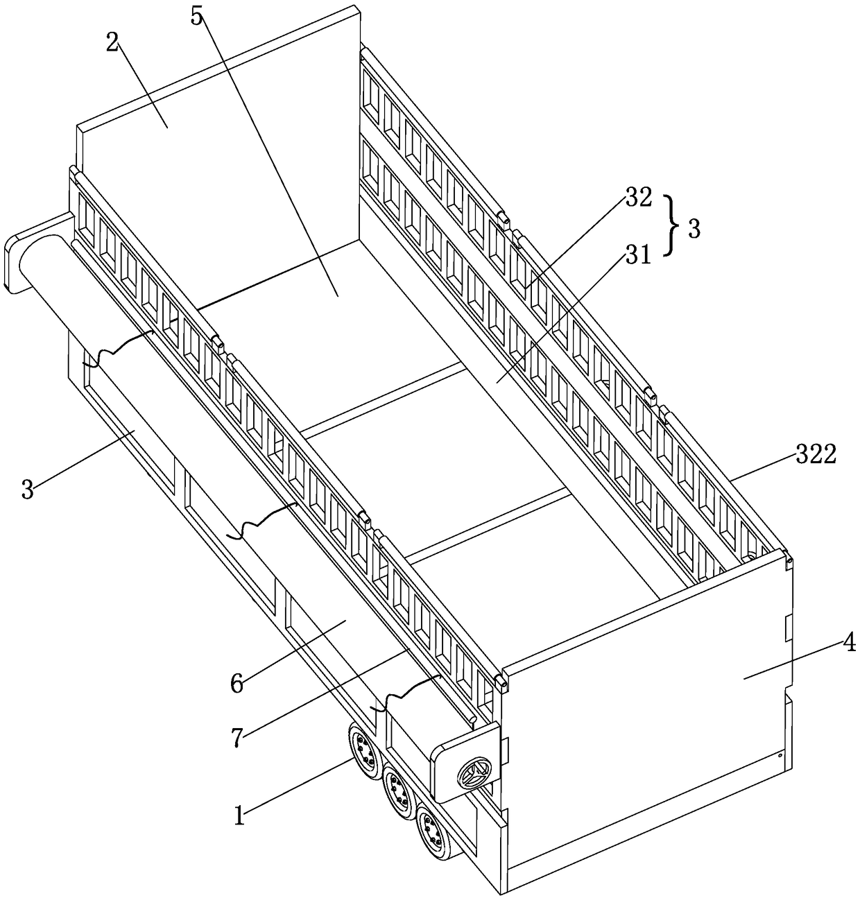
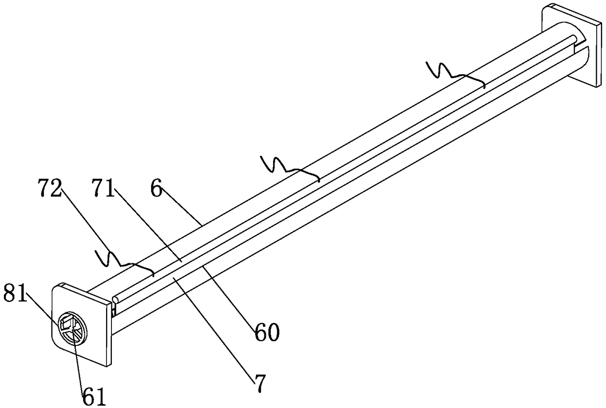
[0037] refer to figure 2 , the tarpaulin storage box 6 is a cylindrical barrel, and its upper side is provided with a tarpaulin inlet and outlet 60 near the car body. , and is as long as tarpaulin storage box 6. The inside of the tarpaulin storage box 6 is provided with a rotating shaft 61 , the rotating shaft 61 is arranged along the length direction of the tarpaulin storage box 6 , and the two ends are connected to the two ends of the tarpaulin storage box 6 in rotation. One side of the tarpaulin 7 is fixed on the rotating shaft 61, and the other side stretches out from the tarpaulin inlet and outlet 60, and remains outside the tarpaulin inlet and outlet 60 all the time. With the rotation of the rotating shaft 61, the tarpaulin 7 can Wound on the rotating shaft 61 and tightly rolled up for storage.
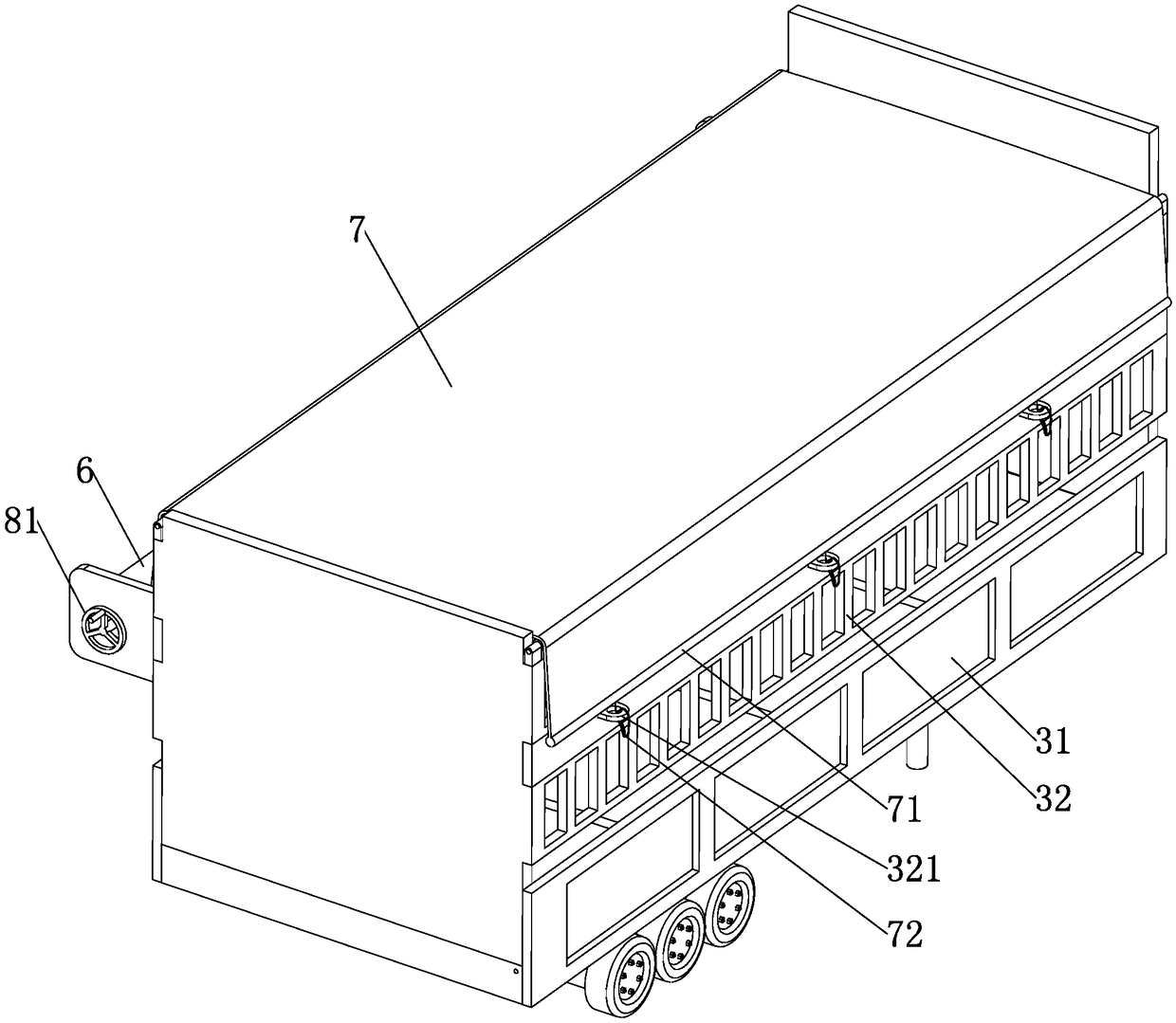
[0038]The tarpaulin 7 is located at the side of the tarpaulin storage box 6 outside and is provided with a clamping rod 71 parallel to the tarpaulin storage box 6, the clampi...
Embodiment 2
[0042] refer to Figure 4 In this embodiment, the driving device includes an elastic belt 82 connected to the two ends of the rotating shaft 61, and a winding shaft 83 arranged below the two ends of the tarpaulin storage box 6. One end of the elastic belt 82 is connected to the winding shaft 82, and the other end is connected to the The end of the rotating shaft 61 can be elongated and wound on the rotating shaft 61, wherein the two ends of the rotating shaft 61 are connected to the two ends of the tarpaulin storage box 6 through bearings, and extend outwards from the two ends, and the elastic belt 82 is wound on the rotating shaft On the end that 61 protrudes, the natural length of elastic belt 82 is less than the length that tarpaulin 7 protrudes.
[0043] The implementation principle of this embodiment is: in combination with the attached figure 1 and 4 In the initial state, the tarpaulin 7 is shrunk in the tarpaulin storage box 6. When the tarpaulin 7 needs to be used, t...
PUM
 Abstract
Description
Claims
Application Information
PatSnap Eureka turns technology decisions into work you can execute. Powered by our Innovation Knowledge Graph, it runs expert workflows across engineering, life sciences, materials and intellectual property. Get your review-ready output in minutes.


