Partition plate oil-driven type engine oil-gas separation device

A separation device, oil and gas separator technology, applied in the direction of engine components, machines/engines, mechanical equipment, etc., can solve the problems of dealing with the influence of small oil droplets, low separation efficiency, no oil droplet adsorption and diversion effects, etc. The effect of improving the efficiency of oil and gas separation

Inactive Publication Date: 2019-01-04
GUANGXI YUCHAI MASCH CO LTD
View PDF9 Cites 1 Cited by
  • Summary
  • Abstract
  • Description
  • Claims
  • Application Information

AI Technical Summary

Problems solved by technology

From the above content, it can be found that the cylinder head cover oil-gas pre-separation device in the prior art is equipped with a rough filter orifice and a circuitous rectification structure, which can be used for oil-gas separation, but super large oil droplets (oil droplets with a diameter greater than 10um) are different from large oil droplets. Oil droplets (referring to oil droplets with a diameter of 2 to 10um) are easy to mix, and do not have the effect of oil droplet adsorption and flow diversion, which will cause the diameter of oil droplets entering the fine filter orifice plate to be still large. Diameter is 0.1~2um) have very big influence; The detour type rectification structure disclosed in the prior art can't solve the problem of secondary breakage (collision splash) of oil droplet that oil-gas mixture produces when high-speed collision, oil droplet flows through collision detour After the rectification structure, it cannot be adsorbed and recovered, and it will still flow to the outlet with the oil-gas mixture, and the separation efficiency is low

Method used


Image

  • Partition plate oil-driven type engine oil-gas separation device
  • Partition plate oil-driven type engine oil-gas separation device
  • Partition plate oil-driven type engine oil-gas separation device

Examples


Embodiment Construction

[0032] In order to make the object, technical solution and advantages of the present invention clearer, the present invention will be further described in detail below through specific embodiments in conjunction with the accompanying drawings. It should be understood that the specific embodiments described here are only used to explain the present invention, not to limit the present invention.

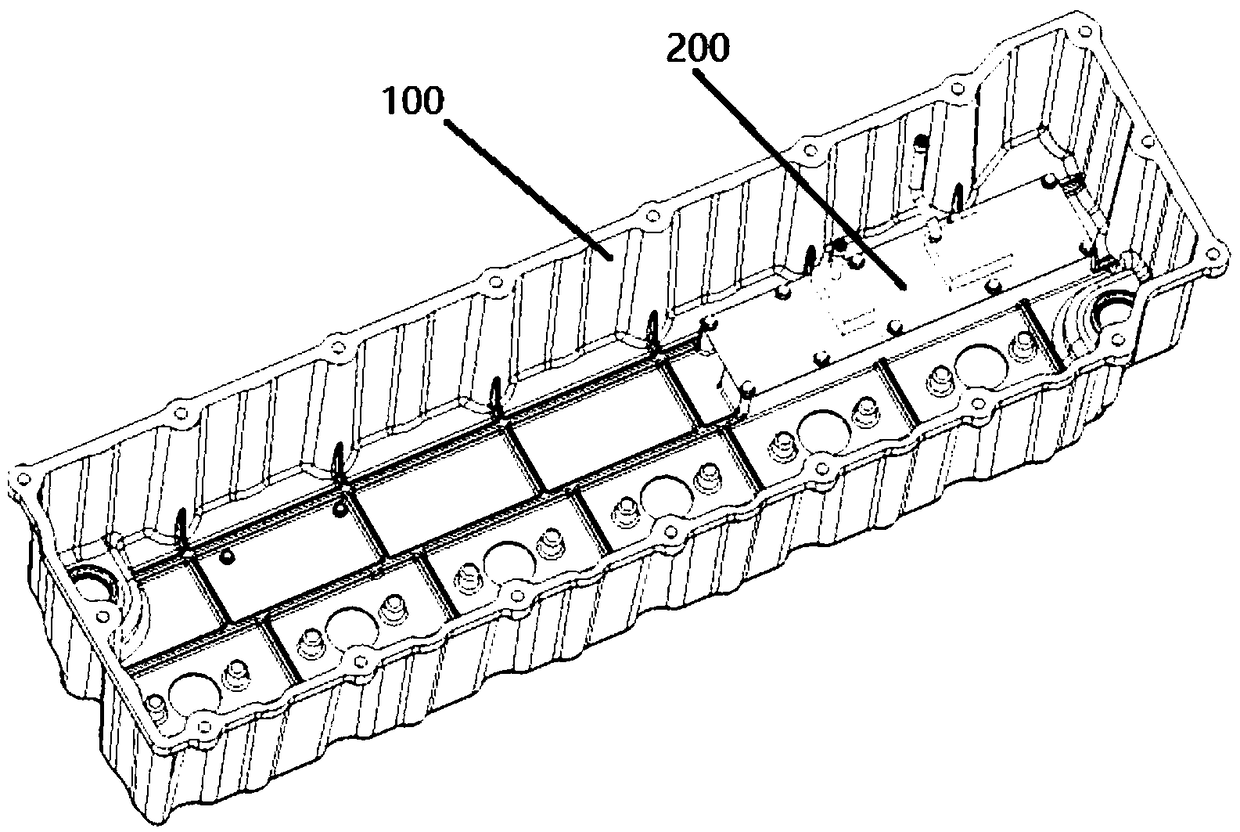
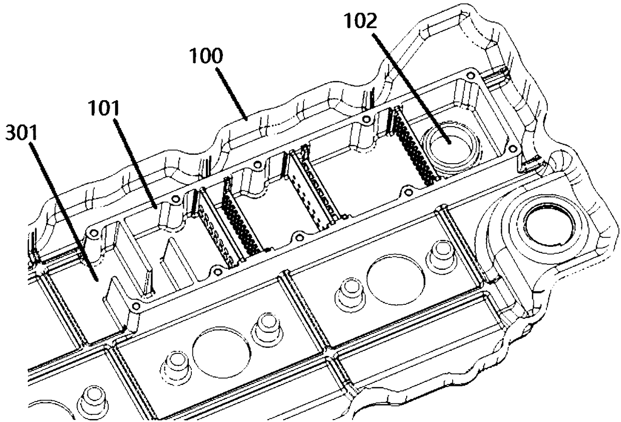
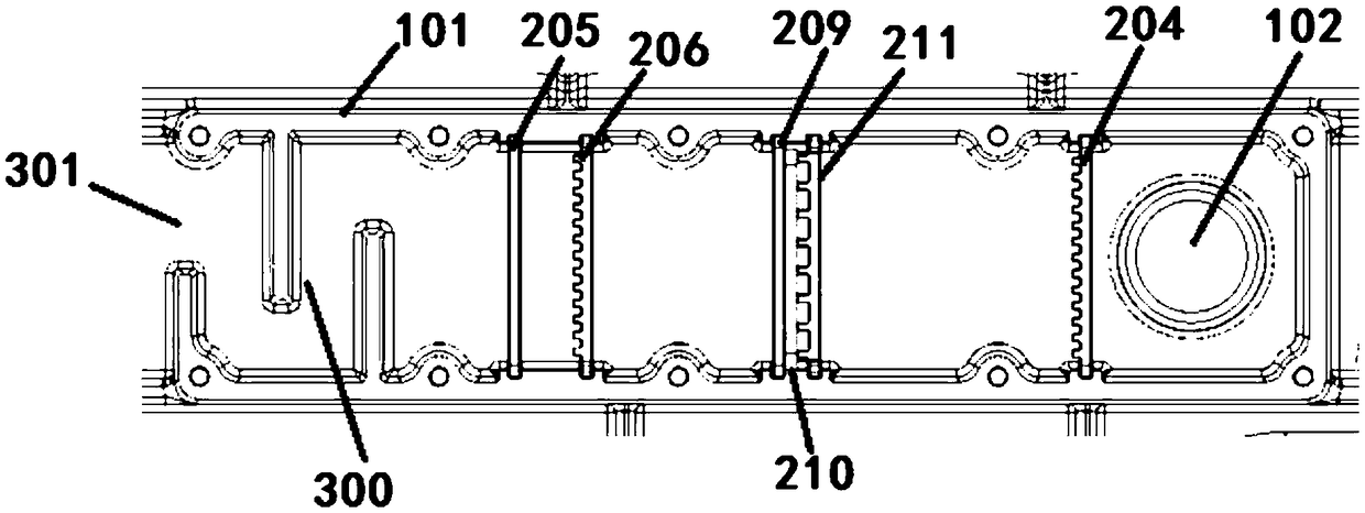
[0033] In an embodiment of the present invention, a separator oil-drive type engine oil-air separation device is provided, the separator oil-drive type engine oil-air separator device includes a pre-separation device and a primary separation device arranged in a mounting groove in the cylinder head cover, and The oil-driven oil-gas separator installed outside the cylinder head cover; the primary separation device can separate part of the oil droplets during the intake stage of the oil-gas mixture, and the oil-gas mixture flows through the primary separation device and then enters the pr...


PUM


Abstract

The invention provides a partition plate oil-driven type engine oil-gas separation device. The partition plate oil-driven type engine oil-gas separation device comprises a pre-separation device arranged in a mounting groove of an air cylinder head cover, an initial separation device arranged in the mounting groove of the air cylinder head cover and an oil-driven type oil-gas separator arranged onthe exterior of the air cylinder head cover; an air inlet hole is formed in the mounting groove, the initial separation device is composed of at least two partition plates, an air vent hole is furtherformed in the air cylinder head cover, and an air outlet pipe connected with the oil-driven type oil-gas separator is arranged on the air vent hole; secondary acceleration can be carried out on oil-gas mixture by the partition plate oil-driven type engine oil-gas separation device, large oil drops and small oil drops are separated correspondingly and flow out through an oil return cavity, and theseparation efficiency is high; and in the adsorption of the small oil drops, a filter element do not have residue blocking due to the impact force of the secondary acceleration, therefore, the filterelement does not needed to be replaced at regular intervals, and the problem of replacing and maintenance at the intervals can be solved.

Description

technical field [0001] The invention belongs to the technical field of oil-gas separation, and in particular relates to an oil-gas separation device for a diaphragm oil-driven engine. Background technique [0002] The high-temperature gas generated by the engine during operation will escape into the crankcase through the gap between the piston group and the cylinder, causing blow-by. The components of blow-by gas are unburned fuel gas, water vapor and exhaust gas. Water vapor condenses in the engine oil to dilute the engine oil and reduce the performance of the engine oil; the sulfur dioxide in the exhaust gas is oxidized by the air to form sulfuric acid, which accelerates the oxidation and deterioration of the engine oil, which will cause corrosion and accelerated wear of engine parts; blow-by gas will also make the crankcase If the pressure is too high, the seal of the crankcase will be damaged, causing the oil to leak; it will accelerate the aging of the oil and reduce t...

Claims


Application Information

Patent Timeline
Patent Type & Authority Applications(China)
IPC IPC(8): F01M13/04
CPCF01M13/04F01M2013/0438F01M2013/0461
Inventor 朱雄覃星念韦福观赵宁宁叶双超余晓强肖刚
Owner GUANGXI YUCHAI MASCH CO LTD
Why Eureka
Try Eureka