
Diaphragm pump

A diaphragm pump and valve seat technology, applied in the direction of pumps, pump components, variable capacity pump components, etc., can solve problems such as difficult processing, reduce processing difficulty, reduce internal space, and facilitate rapid bulging and deflation. Effect

Pending Publication Date: 2019-01-04
XIAMEN KOGE MICRO TECH
View PDF0 Cites 4 Cited by
  • Summary
  • Abstract
  • Description
  • Claims
  • Application Information

AI Technical Summary

Problems solved by technology

However, the smaller the size requirement of the vent channel, the more difficult it is to process the material and the mold

Method used


Image

  • Diaphragm pump
  • Diaphragm pump
  • Diaphragm pump

Examples


Embodiment 1

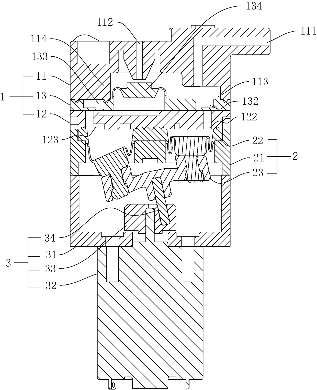
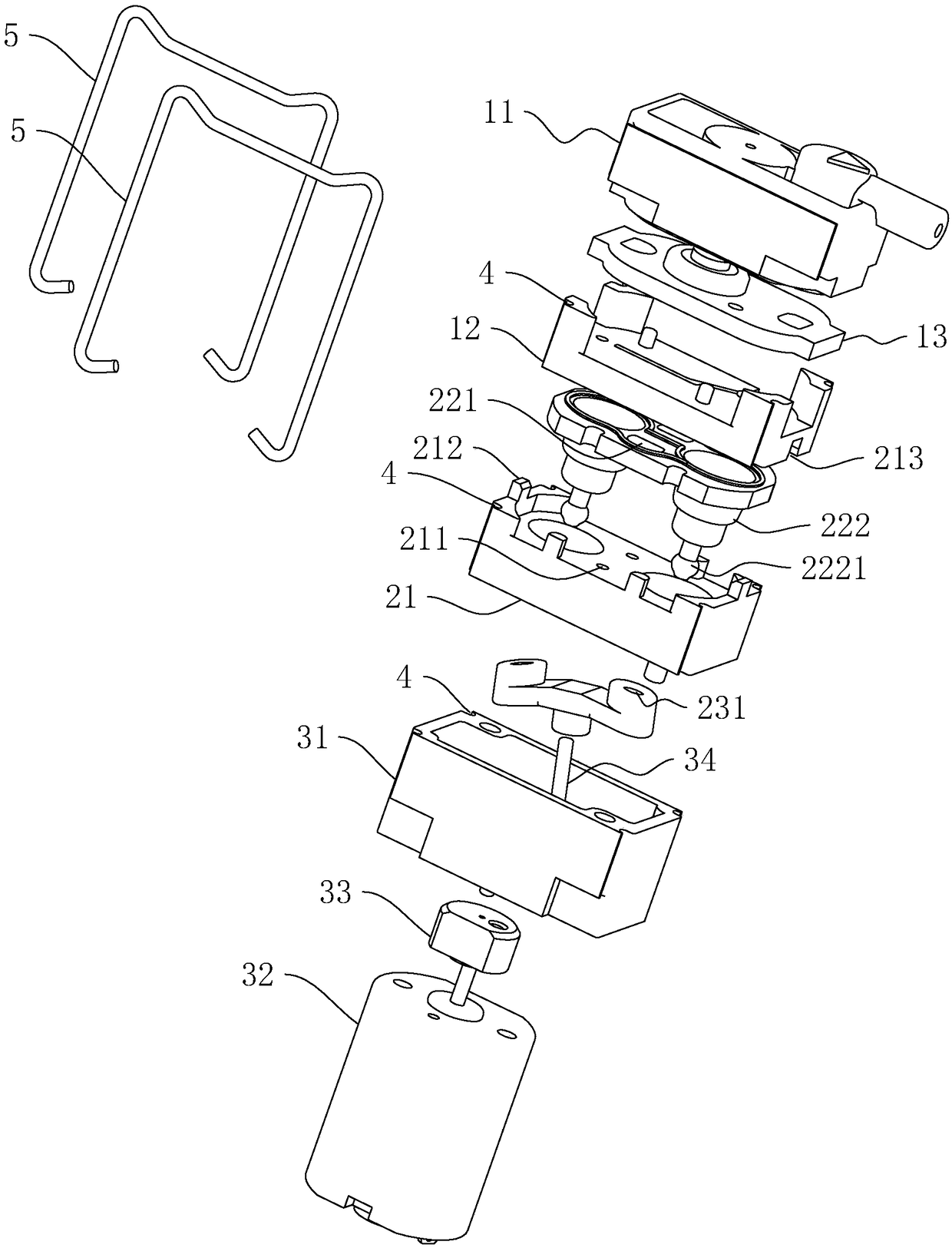
[0037] A diaphragm pump such as figure 1 As shown, it includes an upper cover assembly 1 , a piston assembly 2 and a drive assembly 3 connected sequentially from top to bottom.

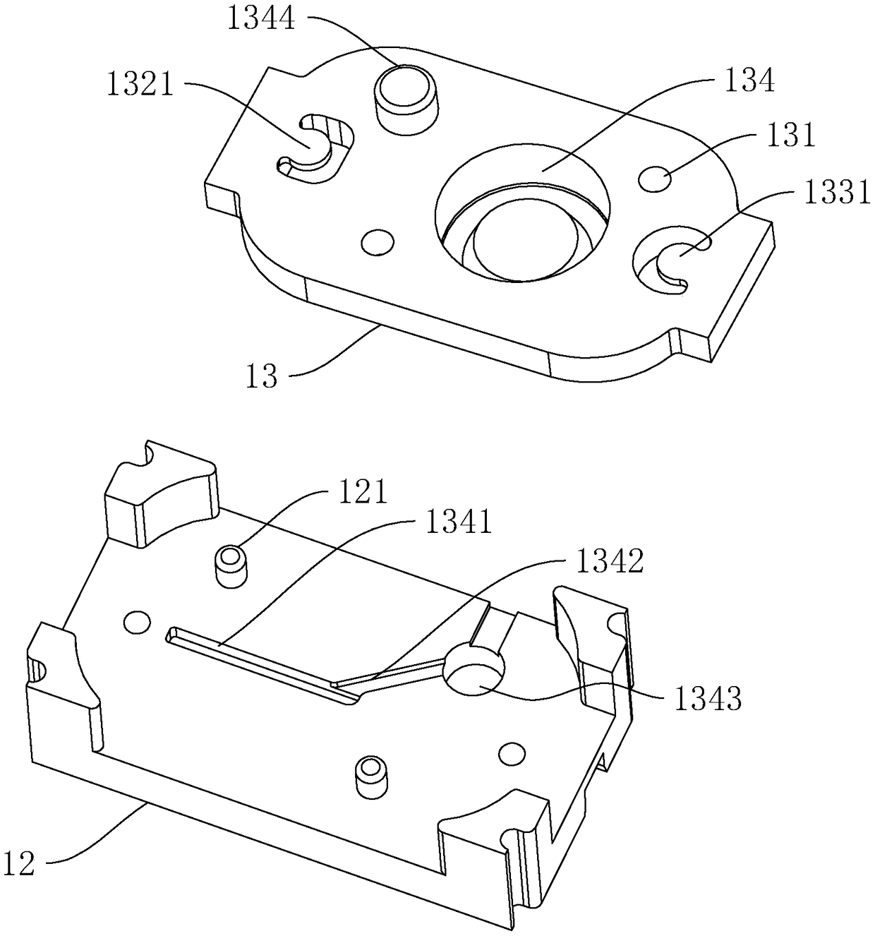
[0038] like figure 1 , 2 As shown, the upper cover assembly 1 includes an upper cover body 11, a valve seat 12 and a valve plate 13, the valve plate 13 is made of rubber material and is arranged between the valve seat 12 and the upper cover body 11, and the upper end of the valve seat 12 is provided with The valve cavity that matches the shape of the valve plate 13 has a positioning protrusion 121 extending upward in the valve cavity. The valve plate 13 is provided with a positioning hole 131 for the insertion of the positioning protrusion 121. Through the positioning protrusion 121 and the positioning hole 131 Cooperating, the installation of the valve plate 13 can be made more stable.

[0039] Further, in order to ensure that the installation position of the valve plate 13 is accurate and reduce ...

Embodiment 2

[0051] A diaphragm pump such as Figure 4 As shown, the difference from Embodiment 1 is that the valve seat 12 is provided with a positioning column 6 extending toward the valve plate 13 and placed in the pressure relief air bag 134, through which the positioning column 6 can prevent the pressure relief air bag 134 from being in a dry state. , reducing the internal space of the pressure relief airbag 134 is conducive to the rapid inflation and deflation of the pressure relief airbag 134.


PUM


Abstract

The invention discloses a diaphragm pump, and belongs to the technical field of pumps. According to the technical scheme, the diaphragm pump comprises an upper cover assembly, a piston assembly and adriving assembly which are connected in sequence from top to bottom, the upper cover assembly is provided with an air outlet, a pressure relief opening and a communication cavity which communicates with the air outlet and the pressure relief opening, the upper cover assembly comprises an upper cover body, a valve base and a valve piece, the valve piece is arranged between the valve base and the upper cover body, the valve piece is provided with a pressure relief air bag used for opening or closing the pressure relief opening, the valve base is provided with an air inlet channel communicating with the pressure relief air bag and an air relief channel for discharging air in the pressure relief air bag, the side, away from the air inlet channel, of the air relief channel communicates with a female part, a male part embedded in the female part is arranged on the valve piece, and the male part and the female part are in gap fit; the machining difficulty of the air relief channel is reduced,and the requirement that the air relief gap of the air relief channel is very small in size is met.

Description

technical field [0001] The invention belongs to the technical field of pumps, and more specifically relates to a diaphragm pump. Background technique [0002] Diaphragm pumps are commonly used to supply compressed air to pressurized targets such as blood pressure monitors, which are pumps that deliver air to the pressurized target by partially deforming a diaphragm made of elastic material. [0003] At present, the diaphragm pump with integrated functions of inflation and deflation needs to be deflated immediately after inflation, and the deflation channel is generally connected to the pressure relief air bag. Among them, in order to avoid the phenomenon of air leakage while pressurizing due to excessive air leakage, the size of the air leakage channel is required to be very small. However, the smaller the size requirement of the vent channel, the more difficult it is to process the material and mold. Contents of the invention [0004] In view of the deficiencies in the ...

Claims


Application Information

Patent Timeline
Patent Type & Authority Applications(China)
IPC IPC(8): F04B45/04F04B45/047F04B39/00F04B39/10
CPCF04B39/00F04B39/1026F04B45/04F04B45/047F04B45/043F04B53/10
Inventor 王四成
Owner XIAMEN KOGE MICRO TECH
Learn More