
Hydraulic oil degassing device for hydraulic mechanism of power circuit breaker

A hydraulic mechanism and circuit breaker technology, applied in high-pressure air circuit breakers, fluid pressure actuating devices, circuits, etc., can solve the problems of inconvenient oil storage tank tilting, inconvenient oil discharge, rigid structure, etc., to achieve convenient and thorough collection and guarantee The effect of conveying speed and reducing labor intensity

Inactive Publication Date: 2019-01-04
柳圣池
View PDF0 Cites 1 Cited by
  • Summary
  • Abstract
  • Description
  • Claims
  • Application Information

AI Technical Summary

Problems solved by technology

[0002] When the hydraulic oil of the hydraulic mechanism of the circuit breaker works for a long time, some gas will be incorporated into the interior, which needs to be removed during use. The existing hydraulic oil degassing device has a rigid structure, which is inconvenient to tilt the oil storage tank It is convenient for the oil inside the oil storage tank to be discharged from the oil outlet, which prolongs the collection time of the treated hydraulic oil, cannot make the collection of hydraulic oil more convenient and thorough, reduces the collection efficiency, increases the labor intensity of the staff, and cannot avoid gas Impurities block the filter screen, affect the exhaust effect, reduce the smoothness of the exhaust gas delivery, cannot guarantee the gas delivery speed, cannot filter the exhaust gas, and the impurities and odors are discharged into the atmosphere to cause pollution

Method used


Image

  • Hydraulic oil degassing device for hydraulic mechanism of power circuit breaker
  • Hydraulic oil degassing device for hydraulic mechanism of power circuit breaker
  • Hydraulic oil degassing device for hydraulic mechanism of power circuit breaker

Examples


Embodiment Construction

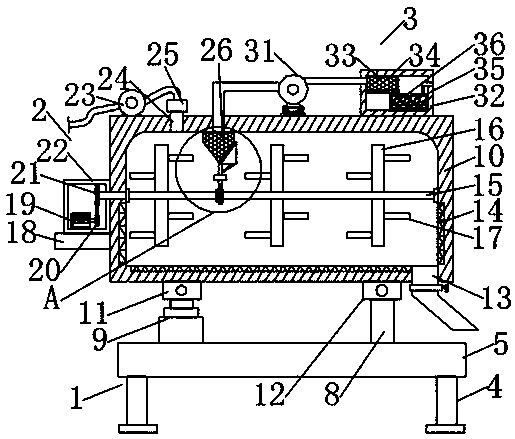
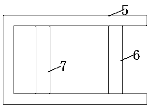
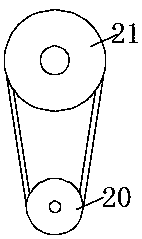
[0020] Such as Figure 1-4 As shown, this specific embodiment adopts the following technical solutions: a hydraulic oil degassing device for a hydraulic mechanism of a power circuit breaker, including a support mechanism 1, a stirring mechanism 2 and a purification mechanism 3, and the top of the support mechanism 1 is provided with a stirring mechanism 2 , the top of the mixing mechanism 2 is provided with a purification mechanism 3, and the support mechanism 1 is composed of a support leg 4, a support frame 5, a first support beam 6, a second support beam 7, a support rod 8 and a hydraulic cylinder 9. The bottom of the support frame 5 is equidistantly fixedly connected with the legs 4, one end of the inner side of the support frame 5 is fixedly connected with the first support beam 6, and the other end of the inner side of the support frame 5 is fixedly connected with the second support beam 7. The top of the first support beam 6 is symmetrically fixedly connected with a sup...


PUM


Abstract

The invention discloses a hydraulic oil degassing device for a hydraulic mechanism of a power circuit breaker. The hydraulic oil degassing device comprises a supporting mechanism, a stirring mechanismand a purifying mechanism, the top of the supporting mechanism is provided with the stirring mechanism, and the purifying mechanism is arranged above the stirring mechanism. According to the hydraulic oil degassing device, an oil storage tank can incline conveniently, oil inside the oil storage tank is conveniently discharged out from an oil outlet, the collection time of treated hydraulic oil isshortened, collection of the hydraulic oil is more convenient and thorough, the collection efficiency is improved, and the labor intensity of a worker is improved. A cleaning brush and a filter net are arranged, filtered materials are cleaned away, blocking of the filter net is avoided, the exhaust effect is influenced, the smoothness of conveying of the exhaust gas is increased, and the gas transporting speed is guaranteed; and a purification tank is arranged, the exhaust gas is conveniently filtered, and impurities and odors are prevented from being discharged into the atmosphere and polluting the atmosphere.

Description

technical field [0001] The invention relates to the technical field of circuit breakers, in particular to a hydraulic oil degassing device for a hydraulic mechanism of an electric circuit breaker. Background technique [0002] When the hydraulic oil of the hydraulic mechanism of the circuit breaker works for a long time, some gas will be incorporated into the interior, and it needs to be removed during use. The existing hydraulic oil degassing device has a rigid structure, which is not convenient for tilting the oil storage tank It is convenient for the oil inside the oil storage tank to be discharged from the oil outlet, which prolongs the collection time of the treated hydraulic oil, cannot make the collection of hydraulic oil more convenient and thorough, reduces the collection efficiency, increases the labor intensity of the staff, and cannot avoid gas Impurities block the filter screen, affect the exhaust effect, reduce the smoothness of the exhaust gas delivery, cannot...

Claims


Application Information

Patent Timeline
Patent Type & Authority Applications(China)
IPC IPC(8): F15B21/041H01H33/34
CPCF15B21/044F15B21/041H01H33/34
Inventor 柳圣池
Owner 柳圣池
Learn More