Lighting device

A lighting device and low beam technology, applied in the field of lighting, can solve the problems of rising temperature of vehicle lamps, reducing service life, slow heat dissipation, etc., and achieving the effects of reducing light loss, improving efficiency, and dispersing heat

Pending Publication Date: 2019-01-04
苏州晶清光电科技有限公司
View PDF0 Cites 3 Cited by
  • Summary
  • Abstract
  • Description
  • Claims
  • Application Information

AI Technical Summary

Problems solved by technology

Due to the high brightness, energy concentration, and high collimation of the laser light source, it has limitations in the application of automobile headlights, especially in the low beam mode, and cannot meet the needs of practical applications. Headlamps generate a lot of heat and dissipate heat slowly, which can easily lead to an increase in the internal temperature of the lamp and reduce its service life

Method used


Image

  • Lighting device
  • Lighting device
  • Lighting device

Examples


Embodiment Construction

[0023] The present invention is described in detail below in conjunction with accompanying drawing:

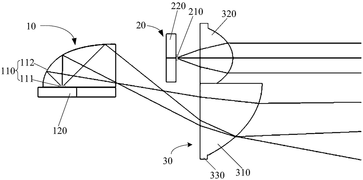
[0024] Such as figure 1 As shown, the present invention provides a lighting device, comprising:

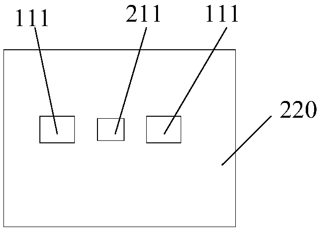
[0025] The low beam module 10 includes a low beam light source and a first heat dissipation unit 120 , the low beam light source includes at least one LED light source 111 and a reflective bowl 112 corresponding to the LED light source 111 . Specifically, in this embodiment, the first heat dissipation unit 120 is located under the low beam light source, and the LED light source 111 can be connected to the first heat dissipation unit 120 through the substrate to quickly dissipate heat. Of course, the first heat dissipation unit 120 can also be located at the low beam. On one side of the light source, the heat is exported through the heat-conducting substrate for rapid heat dissipation. Usually there are 2 to 4 LED light sources 111 in the low-beam light source, and of course ther...


PUM


Abstract

The invention discloses a lighting device. The lighting device comprises a near light module, an far light module and a collimating lens unit, wherein the near light module comprises a near-light light source and a first heat dissipation unit, and the near-light light source comprises at least one LED light source and a reflective bowl corresponding to the LED light source; the far light module islocated in front of the near light module and located above outgoing light of the near light module, and comprises a far-light light source and a second heat dissipation unit; and the collimating lens unit is arranged behind the near light module and the far light module along a light path, the collimating lens unit includes a near light lens corresponding to emergent light of the near light source and an far light lens corresponding to emergent light of the far light source, and the near light lens and the far light lens are formed integrally. By separating the far light module and the nearlight module, the heat dissipation units are separately arranged for heat dissipation, heat can be dissipated efficiently, the heat dissipation efficiency is improved, and the service life is prolonged. The light emitted by the far light source is emergent directly through the far light lens, the arrangement of the reflective bowl is not required, the loss of the light due to the reflection of thereflective bowl is reduced, and the efficiency is further improved.

Description

technical field [0001] The invention relates to the technical field of lighting, in particular to a lighting device. Background technique [0002] Existing automotive headlights are usually halogen lamps, xenon lamps or LED lamps. However, halogen lamps and xenon lamps are not only bulky, but also have low photoelectric conversion efficiency and large beam divergence angles, resulting in low light intensity and limiting the lighting distance. . Although the photoelectric conversion efficiency of LED lamps has been improved compared with halogen lamps and xenon lamps, it is difficult to control the divergence angle within 10°, and in order to increase the lighting distance, multiple LEDs must be arrayed to increase the output power, thereby greatly improving This increases the difficulty of device size, weight and optical adjustment, and the lighting distance in high beam mode cannot meet actual needs. [0003] Laser (semiconductor laser diode) light source has the advantag...

Claims


Application Information

Patent Timeline
Patent Type & Authority Applications(China)
IPC IPC(8): F21S41/16F21S41/141F21S41/25F21S41/30F21S41/40F21S41/663F21W102/13F21Y115/10F21Y115/30
CPCF21S41/16F21S41/141F21S41/25F21S41/30F21S41/40F21S41/663F21W2102/13F21Y2115/10F21Y2115/30
Inventor 邹诚许明
Owner 苏州晶清光电科技有限公司
Why Eureka
Try Eureka