Particle dynamic trajectory measuring system and method based on asynchronous time delay method

A measurement system and particle technology, applied in the field of measurement, can solve the problems of complex and expensive measurement and analysis software, and achieve the effects of cost reduction, small quantity and high efficiency

Inactive Publication Date: 2019-01-04
CHINA JILIANG UNIV
View PDF7 Cites 7 Cited by
  • Summary
  • Abstract
  • Description
  • Claims
  • Application Information

AI Technical Summary

Problems solved by technology

[0003] In order to solve the technical problems of expensive PIV measurement equipment and complex measurement and analysis software in the prior art, the present invention provides a particle dynamic trajectory measurement system and measurement method based on t

Method used


Image

  • Particle dynamic trajectory measuring system and method based on asynchronous time delay method
  • Particle dynamic trajectory measuring system and method based on asynchronous time delay method

Examples


Embodiment 1

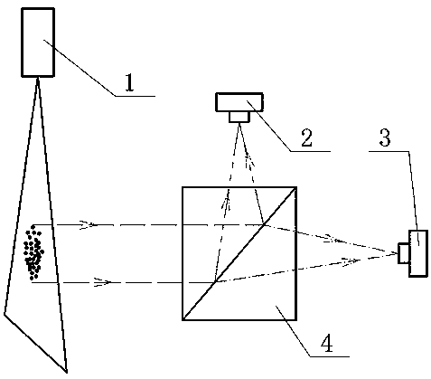
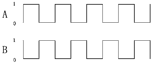
[0016] Such as figure 1 and 2 As shown, a particle dynamic trajectory measurement system based on the asynchronous time-lapse method: including tracer particles, sheet laser light source 1, CCD camera Ⅰ 2, CCD camera Ⅱ 3, half-transparent and half-reflective prism 4 and a computer. The tracer particles are located in the medium solution. The chip laser light source 1 is an ordinary monochromatic laser light source without special requirements. CCD camera Ⅰ2 and CCD camera Ⅱ3 are common industrial cameras with identical parameters, no special requirements. The computer is installed with MATLAB software. The CCD camera I2 is located on the reflective side of the half mirror 4 . The lens of the CCD camera I2 is aimed at the reflective surface of the half-reflective prism 4 . The CCD camera II 3 is located on the transmission side of the half mirror 4 . The lens of the CCD camera II 3 is aimed at the transmissive surface of the half-reflective prism 4 . A sheet laser light ...


PUM

PropertyMeasurementUnit
Particle sizeaaaaaaaaaa

Abstract

The invention provides a particle dynamic trajectory measuring system and a particle dynamic trajectory measuring method based on an asynchronous time delay method, which relate to the technical fieldof measurement. The particle dynamic trajectory measuring method comprises the steps that: a sheet laser light source irradiates tracer particles suspended in a measured plane of a medium solution, light scattered by the tracer particles is projected onto a semi-transparent semi-reflective prism and is decomposed into a reflection image and a transmission image, the reflection image and the transmission image are photographed consecutively and alternately by means of a CCD camera I and a CCD camera II so as form a smearing trajectory diagram of the tracer particles in a time sequence, particle motion trajectories of the sequential tracer particles in the smearing trajectory diagram are extracted by adopting MATLAB software and a dynamic grayscale threshold value based on an Otsu algorithm, and a complete tracer particle dynamic trajectory is obtained through performing additive operation according to the time sequence. The particle dynamic trajectory measuring system and the particledynamic trajectory measuring method solve the technical problems of expensive PIV measurement equipment and complex measurement analysis software in the prior art, and have the beneficial effects of reducing the cost of the PIV measurement technology, decreasing difficulties in system construction and use, being simple in algorithm and ensuring measurement precision.

Description

technical field [0001] The invention relates to the field of measurement technology, in particular to a measurement system for particle dynamic trajectory and a measurement method for the system. Background technique [0002] With the rapid development of industrial camera and machine vision technology, PIV (particle image velocimetry) technology has been widely used in the field of fluid mechanics testing. Since PIV technology has the characteristics of full-field, non-contact, planar two-dimensional, transient and high-precision measurement, it is mainly used to obtain the information of tracer particles in the flow field. Chinese patent application publication number CN102692364A, the application publication date is September 26, 2012, and the invention patent application document named "a dynamic particle measurement device and method based on fuzzy image processing" discloses one of the particle dynamic trajectory measurement devices and methods. It is composed of lig...

Claims


Application Information

Patent Timeline
IPC IPC(8): G01M10/00
CPCG01M10/00
Inventor 孔明董萍单良王道档赵军包福兵于明州
Owner CHINA JILIANG UNIV
Why Eureka
Try Eureka