
A method for acquiring three-dimensional image information of an object based on a micro satellite constellation

A micro-satellite, three-dimensional image technology, applied in the field of spacecraft attitude control, can solve the problems of narrow application direction, worrying quality, lack of application and so on

Active Publication Date: 2019-01-04
NORTHWESTERN POLYTECHNICAL UNIV
View PDF4 Cites 10 Cited by
  • Summary
  • Abstract
  • Description
  • Claims
  • Application Information

AI Technical Summary

Problems solved by technology

It is mainly used for communication, remote sensing of the earth, interplanetary exploration, scientific research and technical experiments. Compared with previous large satellites, microsatellites have many advantages such as small size, light weight, short development cycle, low cost, and flexible launch methods. However, it also brings the disadvantages of small load, low function, poor performance, and narrow application direction
In particular, micro-satellites with smaller mass and volume levels, such as picostars and flying stars, have existing application areas only for scientific or technical verification in the field of scientific research and technical experiments, and lack practical functional applications.
[0004] The application load of existing picostar or flying star-level microsatellites is generally only a common commercial camera, and the results in practical applications are often very unsatisfactory. The attitude control system applied under the limited load and energy is difficult to ensure the stability of its own attitude during the process of capturing image information; on the other hand, common commercial cameras are generally difficult to avoid or eliminate the impact of the harsh space environment
Under the influence of various factors, the image information obtained by a single micro-satellite is often very limited, the quality is worrying, and it has no practical significance

Method used


Image

  • A method for acquiring three-dimensional image information of an object based on a micro satellite constellation
  • A method for acquiring three-dimensional image information of an object based on a micro satellite constellation
  • A method for acquiring three-dimensional image information of an object based on a micro satellite constellation

Examples


Embodiment Construction

[0017] The technical solution of the present invention will be further described below in conjunction with the accompanying drawings and specific embodiments.

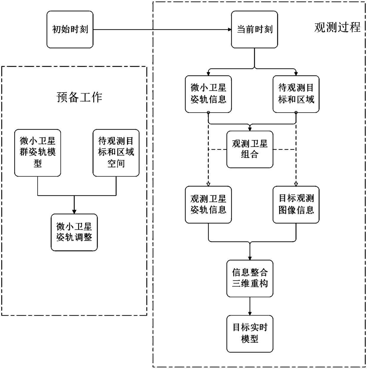
[0018] The simple and easy calculation process of the inventive method, with reference to figure 1 :

[0019] (1) Based on the attitude and orbit information of the micro-satellite formation and the given position of the 3D target to be observed in the regional space, preparatory work is carried out:

[0020] Initially adjust the attitude and orbit of the micro-satellite formation, adjust the micro-satellite formation configuration to the required good observation pose state, that is, the number of micro-satellites in the observation pose state is the largest and the satellite formation configuration is optimal, and at On this basis, the switching time sequence of the tiny micro-camera is designed according to the time-varying information of each micro-satellite's possible observation domain and the relative pose rela...


PUM


Abstract

The invention discloses a method for obtaining three-dimensional image information of an object based on a micro satellite group, which comprises the following steps: step S1, each micro satellite inthe micro satellite group carries out observation work according to a preset working time sequence, and obtains image information of the object; step S2, a satellite observation combination is obtained according to the relative orbit and attitude relationship between the observation area of the micro satellite and the target; step S3, each satellite observation combination obtains the image information of the target, and constructs the three-dimensional image information of the target, and constructs the real-time model of the target in the space environment. By synthesizing the images acquired by a large number of micro-satellites, analyzing and integrating the image information about the target and its space, the corresponding three-dimensional model of the target and space environment is constructed, which overcomes the shortcoming of limited and useless image information acquired by single micro-satellite.

Description

technical field [0001] The invention belongs to the technical field of spacecraft attitude control; in particular, it relates to a method for acquiring target three-dimensional image information based on microsatellite groups. Background technique [0002] With the rapid development of aerospace technology, spacecraft such as artificial satellites, space stations, and space shuttles have been put into use one after another. However, huge expenses and expensive costs have always restricted the development of aerospace technology. After the end of the Cold War, aerospace science and technology gradually shifted from military application to economic construction, and commercial operations prompted aerospace science and technology to reduce costs and improve efficiency. On the other hand, the advancement of microelectronics technology, the development of lightweight materials and the emergence of high-power solar cells have made it possible to miniaturize various instruments an...

Claims


Application Information

Patent Timeline
Patent Type & Authority Applications(China)
IPC IPC(8): G06T7/70G06T15/00
CPCG06T7/70G06T15/005
Inventor 袁源赵迪王明明孙冲崔尧马川车德佳
Owner NORTHWESTERN POLYTECHNICAL UNIV
Learn More