
Teaching device for simulating RLC oscillation circuit

A teaching device and oscillating circuit technology, applied in teaching models, educational tools, instruments, etc., can solve problems such as difficult for students to see intuitively and inconvenient for teaching

Inactive Publication Date: 2019-01-04
CHANGZHOU COLLEGE OF INFORMATION TECH
View PDF0 Cites 3 Cited by
  • Summary
  • Abstract
  • Description
  • Claims
  • Application Information

AI Technical Summary

Problems solved by technology

However, since the RLC oscillating circuit is an electronic circuit, its characteristics are manifested in an electromagnetic form, and it is difficult for students to see it intuitively during teaching, which is inconvenient for teaching

Method used


Image

  • Teaching device for simulating RLC oscillation circuit
  • Teaching device for simulating RLC oscillation circuit

Examples


Embodiment Construction

[0017] In order to facilitate the understanding of the present invention, the present invention will be described more fully below with reference to the associated drawings. Preferred embodiments of the invention are shown in the accompanying drawings. However, the present invention can be embodied in many different forms and is not limited to the embodiments described herein. On the contrary, the purpose of providing these embodiments is to make the disclosure of the present invention more thorough and comprehensive.

[0018] It should be noted that when an element is referred to as being “fixed” to another element, it can be directly on the other element or there can also be an intervening element. When an element is referred to as being "connected to" another element, it can be directly connected to the other element or intervening elements may also be present. The terms "vertical," "horizontal," "left," "right," and similar expressions are used herein for purposes of ill...


PUM


Abstract

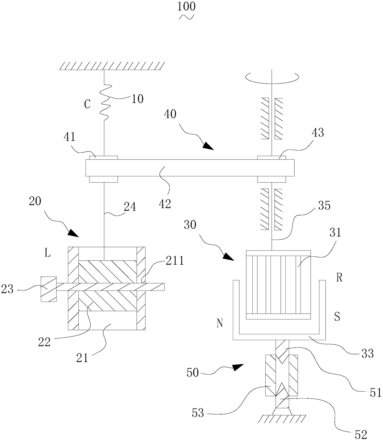
The invention relates to a teaching device for simulating RLC oscillation circuit. The teaching device for simulating the RLC oscillation circuit comprises a torsion spring, a rotating assembly and anelectromagnetic induction assembly, the rotary assembly includes a limiting barrel, Energy-storage rotate wheel and force applying brace, the energy storage rotary wheel is rotatably arranged in thelimiting cylinder, the energy storage rotary wheel is connected with the torsion spring, the force applying brace is used for applying rotational motive force to the energy storage rotary wheel. The electromagnetic induction assembly includes a squirrel cage rotor and a magnetic body, the squirrel cage rotor interacting with the energy storage rotary wheel, the magnetic body disposed adjacent to the squirrel cage rotor for adjusting rotational resistance of the squirrel cage rotor. The electromagnetic induction assembly includes a squirrel cage rotor and a magnetic body, wherein the magnetic body is disposed adjacent the squirrel cage rotor for adjusting rotational resistance of the squirrel cage rotor. The teaching device of the analog RLC oscillation circuit is intuitive and convenient for teaching.

Description

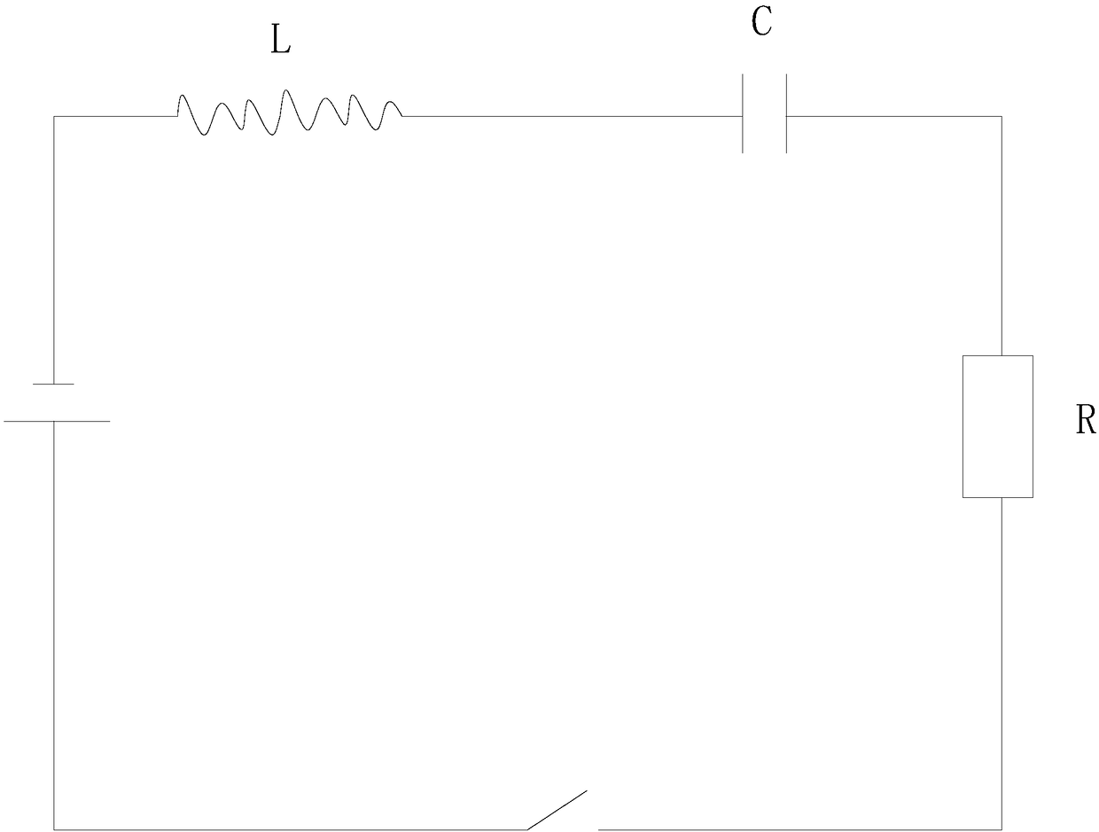
technical field [0001] The invention relates to a teaching device for simulating an RLC oscillating circuit. Background technique [0002] The RLC oscillating circuit is a circuit structure composed of a resistor R, an inductor L, and a capacitor C. see figure 1 , when the resistance value is adjusted to 0, the RLC oscillating circuit becomes an LC oscillating circuit, in which the electricity on the capacitor C can be repeatedly stored and released, and can be used as an electric resonator to store the energy oscillating when the circuit resonates. When the inductance L is removed, the RLC oscillating circuit becomes an RC circuit. However, since the RLC oscillating circuit is an electronic circuit, its characteristics are manifested in an electromagnetic form, and it is difficult for students to see it intuitively during teaching, which is inconvenient for teaching. Contents of the invention [0003] Based on this, it is necessary to provide a teaching device for simu...

Claims


Application Information

Patent Timeline
IPC IPC(8): G09B23/18
CPCG09B23/183
Inventor 邓志辉嵇明军裴志坚王军
Owner CHANGZHOU COLLEGE OF INFORMATION TECH
Learn More