A contact cooling motor

A contact type, motor housing technology, applied in the direction of electromechanical devices, electrical components, electric components, etc., can solve the problems of dust entry, poor heat radiation effect, poor motor ventilation, etc.

Active Publication Date: 2020-10-09
ZHEJIANG XINLI ELECTRIC APPLIANCE TECH CO LTD
View PDF12 Cites 0 Cited by
  • Summary
  • Abstract
  • Description
  • Claims
  • Application Information

AI Technical Summary

Problems solved by technology

[0003] However, the equipment that uses the motor as power will generate heat when it is working. The heat is caused by poor ventilation of the motor and a lot of dust inside. In order to improve the heat dissipation performance of the traditional motor, a fan is usually installed inside the motor to speed up the heat dissipation by taking away the hot air through the airflow, but the heat dissipation effect of the heat radiation is poor; in addition, when the fan is used for heat dissipation, in order to reduce dust entering The motor casing, often the vents on the motor casing are set on the side wall of the fan outlet end. When the fan rotates, a negative pressure will be formed inside the motor casing. At this time, the air flowing into the motor casing and the air flowing to the outside of the motor casing The air passes through the ventilation openings, resulting in a small wind power of the fan and poor heat dissipation performance; if an air intake hole is provided on the peripheral surface of the motor casing, it is easy to cause dust to enter when the motor is not in use

Method used


Image

  • A contact cooling motor
  • A contact cooling motor
  • A contact cooling motor

Examples


Embodiment

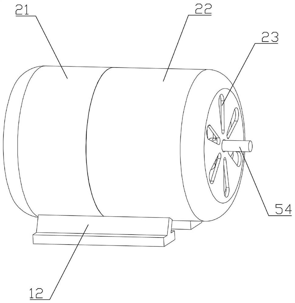
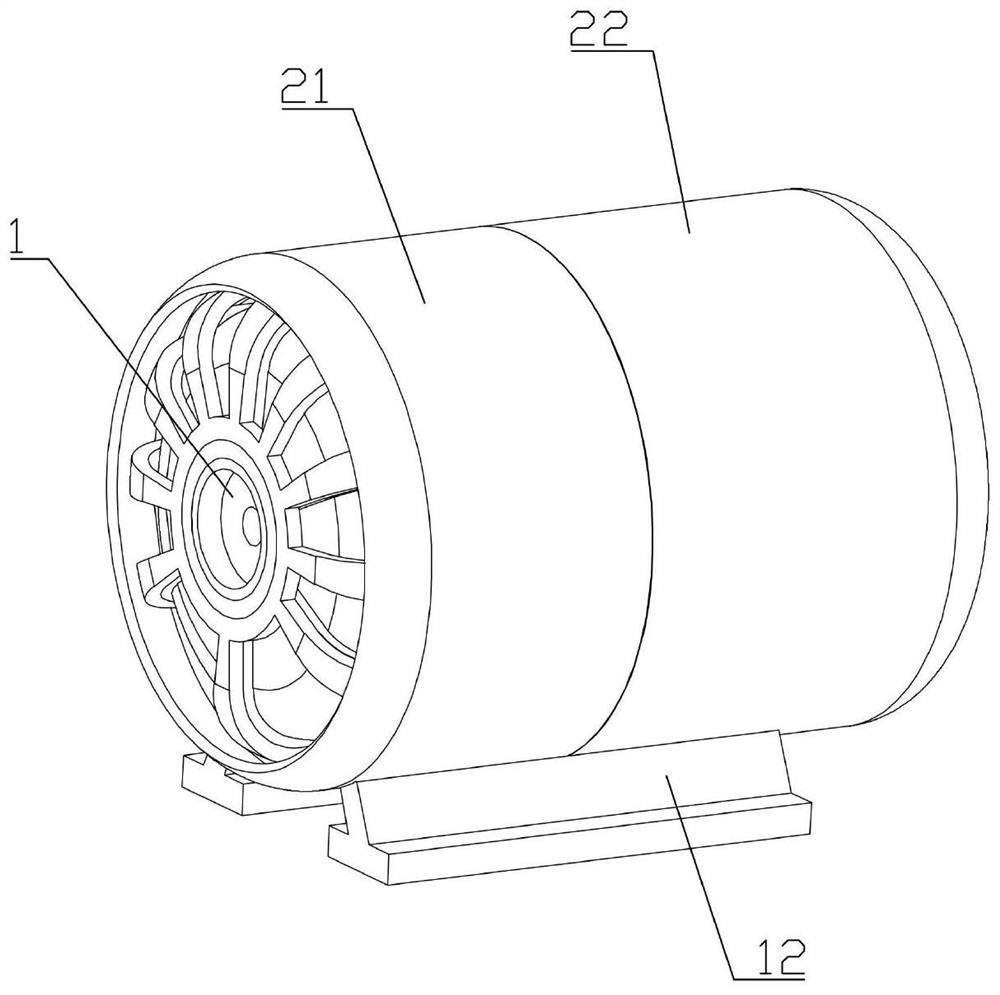
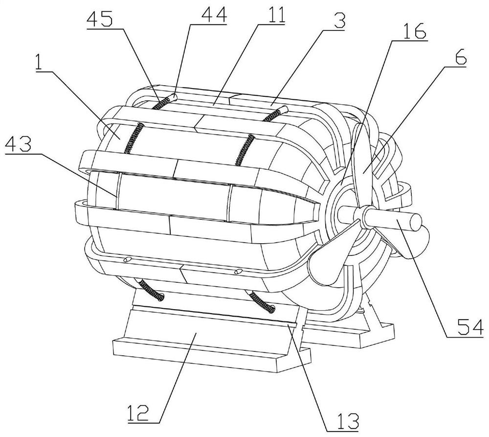
[0030] Such as Figure 1-7As shown, a contact heat dissipation motor of the present invention includes a motor body 1, and the motor body 1 includes a motor housing 51, a stator 52, a rotor 53 and an output shaft 54 ​​installed in the motor housing 51, and a base is installed on the motor housing 51 12. The exterior of the motor casing 51 is integrally formed with a plurality of heat-conducting protrusions 11 in the axial direction, and the heat-absorbing cover 3 is installed on the motor casing 51. The heat-absorbing cover 3 includes a plurality of heat-absorbing strips and connecting rings 35, wherein the heat-absorbing strips are Copper blocks, and the top of the heat-absorbing strip has multiple slits, the heat-absorbing strip is fixedly installed on the connecting ring 35, the two ends of the motor housing 51 are integrally formed and the coaxial center is provided with a mounting ring 15, and the connecting ring 35 is sleeved on the mounting ring 35. On the ring 15, a be...


PUM


Abstract

The invention belongs to the technical field of electric machines, A contact heat dissipation motor include a motor body, the motor body includes a motor housing and a stator mounted in the motor housing, rotor and output shaft, A plurality of heat conduction protrusions are integrally formed on the exterior of the motor shell and axially arranged, A heat-absorbing cover is arranged on that motorhouse, the heat absorbing cover includes a plurality of heat absorbing strips and a connecting ring, the heat absorbing strip is fixedly installed on the connecting ring, At both end of that motor shell, the coaxial center is integrally for with a mounting ring, The heat conduction protrusion and the heat absorbing strip are gap-matched, the heat conduction protrusion is provided with a first arcgroove, the heat absorbing strip is provided with a second arc groove, the heat conduction protrusion is installed with a heat insulating block in the first arc groove, a memory spring is fixedly installed on the heat insulating block, and the memory spring is fixedly installed in the second arc groove in the heat conduction strip. It has good heat dissipation, while completely avoiding dust intothe motor interior.

Description

technical field [0001] The invention belongs to the technical field of motors, and in particular relates to a contact heat dissipation motor. Background technique [0002] Motor (English: Electricmachinery, commonly known as "motor") refers to an electromagnetic device that realizes the conversion or transmission of electric energy according to the law of electromagnetic induction. In the circuit, it is represented by the letter M (the old standard is D). Its main function is to generate driving torque as a power source for electrical appliances or various machinery. The generator is represented by the letter G in the circuit. Its main function is to convert electrical energy into mechanical energy. [0003] However, the equipment that uses the motor as power will generate heat when it is working. The heat is caused by poor ventilation of the motor and a lot of dust inside. In order to improve the heat dissipation performance of the traditional motor, a fan is usually in...

Claims


Application Information

Patent Timeline
Patent Type & Authority Patents(China)
IPC IPC(8): H02K9/22H02K5/20H02K9/06
CPCH02K5/20H02K9/06H02K9/22
Inventor 吴正灿孙宝球邵文华
Owner ZHEJIANG XINLI ELECTRIC APPLIANCE TECH CO LTD
Why Eureka
Try Eureka