Multi-mode radio frequency front-end circuit and control method therefor

A radio frequency front-end, multi-mode technology, applied in electrical components, transmission systems, etc., to avoid over-saturation of reception, avoid frequent jumps, and maintain stability

Active Publication Date: 2019-01-04
安徽矽磊电子科技有限公司
View PDF8 Cites 9 Cited by
  • Summary
  • Abstract
  • Description
  • Claims
  • Application Information

AI Technical Summary

Problems solved by technology

[0007] Furthermore, when the power amplifier adopts a differential-single-ended structure and the low-noise amplifier adopts a single-

Method used


Image

  • Multi-mode radio frequency front-end circuit and control method therefor
  • Multi-mode radio frequency front-end circuit and control method therefor
  • Multi-mode radio frequency front-end circuit and control method therefor

Examples


Embodiment Construction

[0034] In order to make the purpose, technical solution and advantages of the present invention more clear, the embodiments of the present invention will be described in detail below in conjunction with the accompanying drawings. It should be noted that, in the case of no conflict, the embodiments in the present application and the features in the embodiments can be combined arbitrarily with each other.

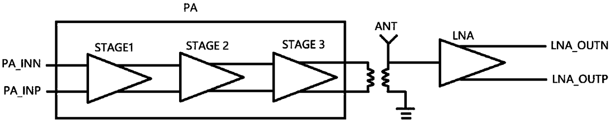
[0035] Such as image 3 As shown, it shows the basic circuit structure of the radio frequency front-end circuit of the present invention, wherein the power amplifier PA is composed of three amplifying units: input stage STAGE 1, intermediate stage STAGE 2 and output stage STAGE3, and the PA is a fully differential structure . The input of the PA receives the differential signal from the upstream transmit circuit. The upstream transmitting circuit may include a baseband controller, a digital or analog frequency converter connected in sequence; a local oscillator signal gener...


PUM


Abstract

The invention proposes a multi-mode radio frequency front-end circuit, and the circuit comprises a power amplifier and a low-noise amplifier, which are coupled to an antenna. The power amplifier is atleast formed by the combination of a first amplifier stage and a second amplifier stage. The output of the first amplifier stage is coupled to the output end of the low-noise amplifier through a first switch to form a first additional loop. The output end of the low-noise amplifier is also connected with the input end through a second switch to form a second additional loop. A mode switching control circuit is used for controlling the on/off states of the first and second switches, and also controlling the first amplifier stage, the second amplifier stage and the low-noise amplifier to be inthe working state or forbidden state, thereby enabling the radio frequency front-end circuit to be in a required working mode. According to the above circuit structure, the circuit design is simplified, and the improved radio frequency front-end circuit to have the high-efficiency advantage of a low-power output mode of the power amplifier and a low noise coefficient of the low-noise amplifier ina low-gain mode.

Description

technical field [0001] The invention relates to the field of communication signal processing, in particular to a multi-mode radio frequency front-end circuit and a control method thereof. Background technique [0002] figure 1 It shows a typical circuit diagram of a Wi-Fi communication product in the prior art. The entire radio frequency circuit is composed of five modules, including a wireless transceiver module, a transmitting front-end module, a transceiver switch module, a low-noise amplifier module and an antenna module, such as As shown in the figure, the transmitter front-end module is inside the dotted line box. A wireless transceiver (Radio Transceiver) is generally one of the core devices of a design. In addition to being closely related to the radio frequency circuit, it is generally related to the CPU. Here, we only focus on some content related to the radio frequency circuit. When sending a signal, the transceiver itself will directly output a weak radio frequ...

Claims


Application Information

Patent Timeline
IPC IPC(8): H04B1/40H04B1/44H04B1/04
CPCH04B1/04H04B1/40H04B1/44H04B2001/0408
Inventor 王晗
Owner 安徽矽磊电子科技有限公司
Why Eureka
Try Eureka