Abnormality detection apparatus and vehicle system
An anomaly detection and anomaly technology, applied to vehicle parts, transportation and packaging, character and pattern recognition, etc., to reduce the processing burden
- Summary
- Abstract
- Description
- Claims
- Application Information
AI Technical Summary
Problems solved by technology
Method used
Image

Examples
no. 1 example
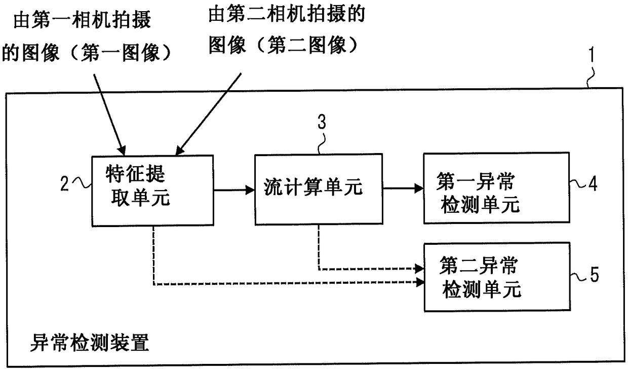
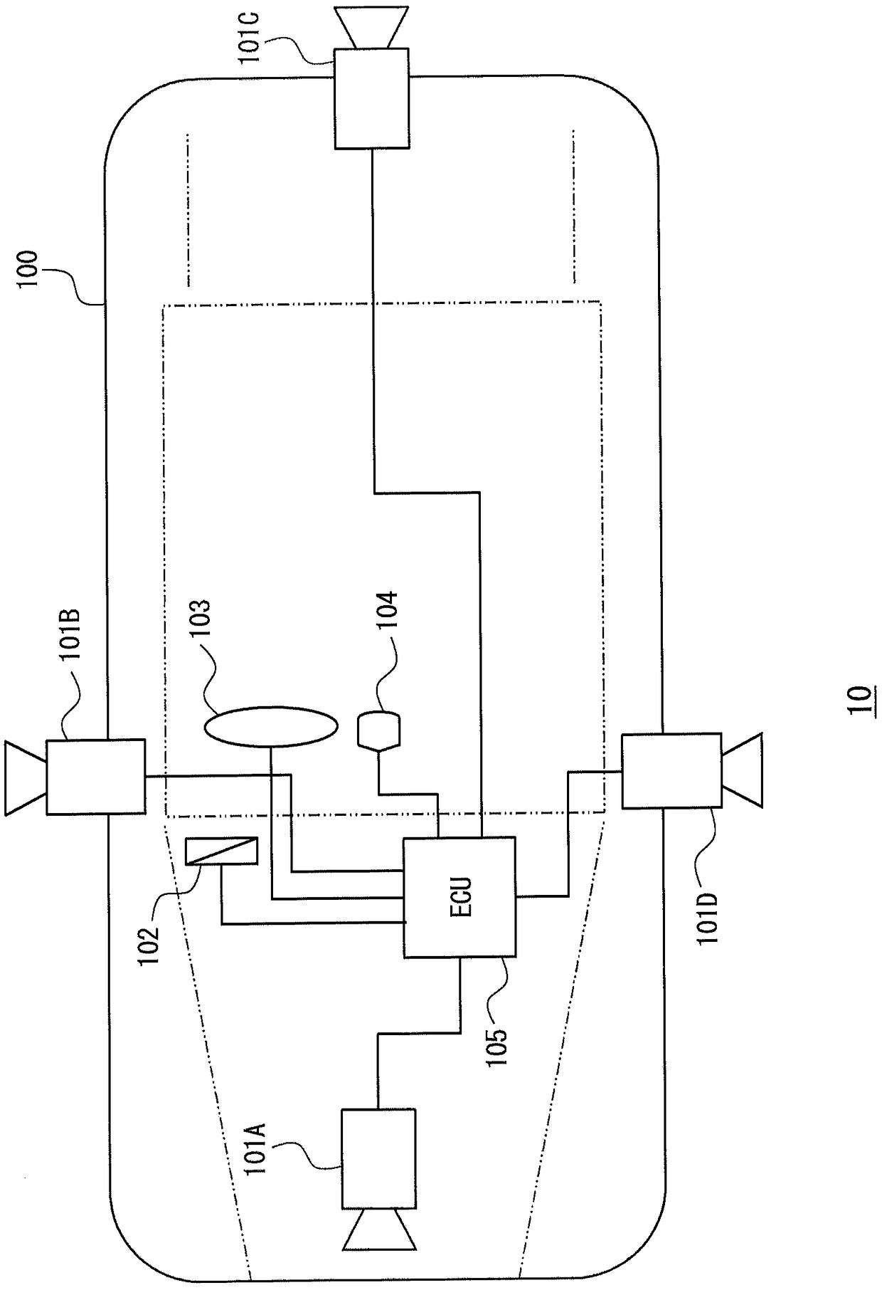
[0037] Next, details of the embodiment are described. figure 2 is a schematic diagram showing an example of a positional relationship between elements constituting the vehicle system 10 according to the first embodiment. The vehicle system 10 includes cameras 101A to 101D as information input devices installed in the vehicle 100 and other components installed in the vehicle 100 . Note that in figure 2 In the example shown, four cameras are shown. However, the vehicle system 10 needs to be equipped with only two or more cameras. exist figure 2 In the example shown, control means such as brakes 102 and steering wheel 103 and information output means such as warning display means 104 are shown as further components. Furthermore, the vehicle system 10 includes an ECU (Electronic Control Unit) 105 .
[0038] The cameras 101A to 101D, the brake 102, the steering wheel 103, and the warning display unit 104 are connected to the ECU 105 which recognizes information, determines ...
no. 2 example
[0104] Next, a second embodiment is described. In the first embodiment, the comparison area has a rectangular shape. That is, the second abnormality detection unit 203 uses a pre-designated rectangular area (for example, rectangular area R4 A or R4 B ) to create the frequency distribution of the optical flow of the feature points. In contrast, in the second embodiment, the comparison area has a circular shape. That is to say, in the second embodiment, by pre-designated circular areas in the overlapping extraction area (for example, Figure 8 The rectangular region R5 in A or R5 B ) to create the frequency distribution of the optical flow of the feature points. Hereinafter, a second embodiment is described. However, descriptions of configurations and operations similar to those of the first embodiment are omitted.
[0105] As described above, when the shooting directions of a plurality of cameras to be compared are different from each other, it is necessary to create a ...
no. 3 example
[0109] Next, a third embodiment is described. In the first and second embodiments, abnormality is determined based only on information obtained from images. In contrast, in the present embodiment, information on the movement of the vehicle is considered for determining abnormality of the image acquired from the camera. Hereinafter, a third embodiment is described. However, descriptions of configurations and operations similar to those of the first and second embodiments are omitted.
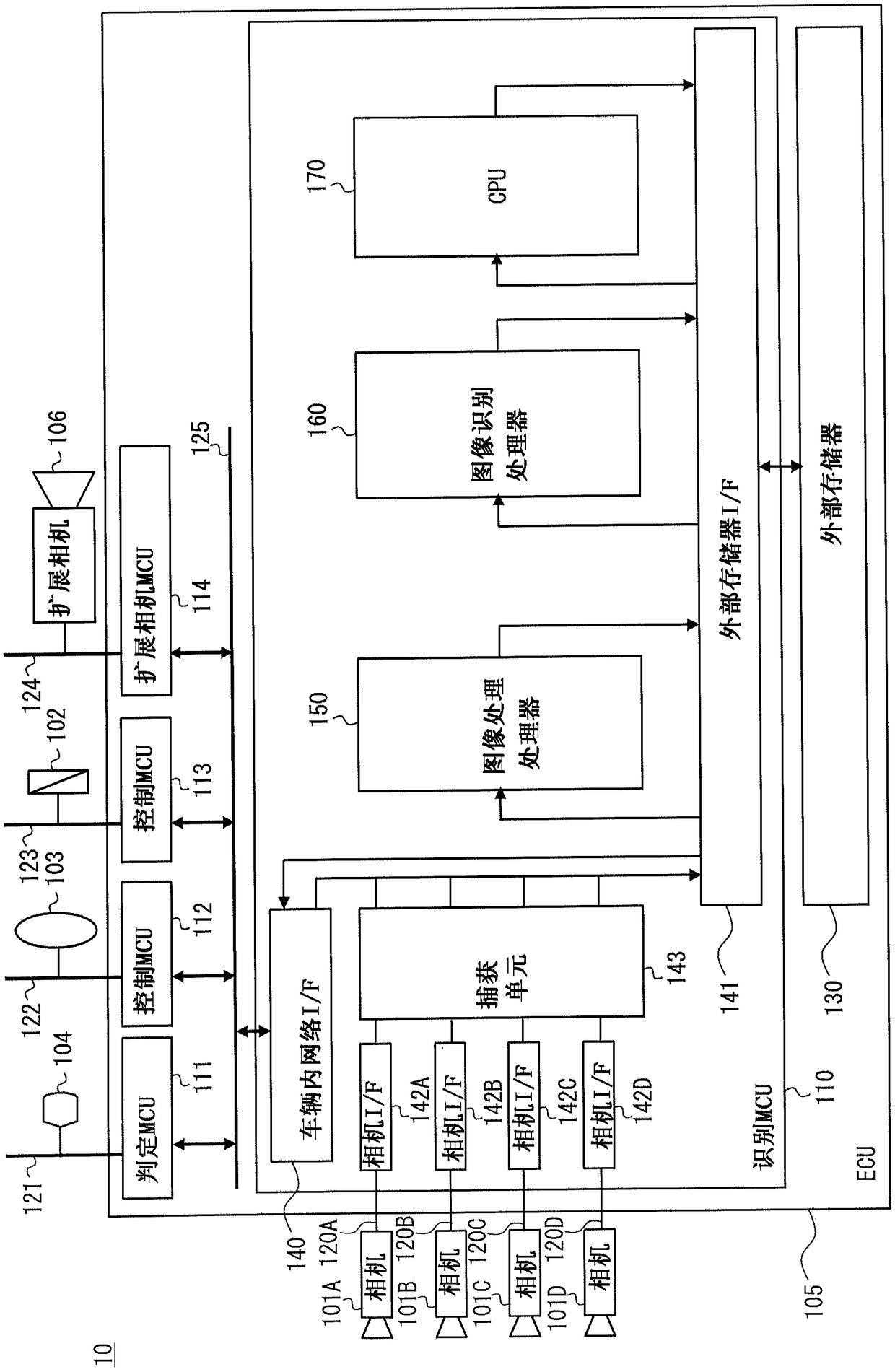
[0110] Figure 9 is a block diagram showing an example of the hardware configuration of the vehicle system 11 according to the third embodiment. Vehicle system 11 is different from image 3 The vehicle system 10 shown is characterized in that the vehicle system 11 further includes a GNSS device 107 and a positioning MCU 115 .
[0111] The GNSS device 107 is a terminal for obtaining positioning information of the vehicle 100 based on a GNSS (Global Navigation Satellite System) signal. A posi...
PUM
 Abstract
Description
Claims
Application Information
 - R&D
- Intellectual Property
- Life Sciences
- Materials
- Tech Scout
- Unparalleled Data Quality
- Higher Quality Content
- 60% Fewer Hallucinations
Browse by: Latest US Patents, China's latest patents, Technical Efficacy Thesaurus, Application Domain, Technology Topic, Popular Technical Reports.
© 2025 PatSnap. All rights reserved.Legal|Privacy policy|Modern Slavery Act Transparency Statement|Sitemap|About US| Contact US: help@patsnap.com