
robot controller

一种控制装置、机器人的技术,应用在程序控制机械手、机械手、制造工具等方向,能够解决作业效率降低等问题

Active Publication Date: 2021-08-13
MITSUBISHI ELECTRIC CORP
View PDF8 Cites 0 Cited by
  • Summary
  • Abstract
  • Description
  • Claims
  • Application Information

AI Technical Summary

Problems solved by technology

[0003] In Patent Document 1, which is an example of the prior art, the robot stops the operation every time the operator intervenes in the operation of the robot, and the work efficiency is reduced. For such a problem, the following content is disclosed. The current position and moving speed of the two predict the future position of both the operator and the robot, and judge the possibility of contact between the robot and the operator based on the predicted value. without stopping the robot's motion

Method used


Image

  • robot controller
  • robot controller
  • robot controller

Examples


Embodiment approach 1

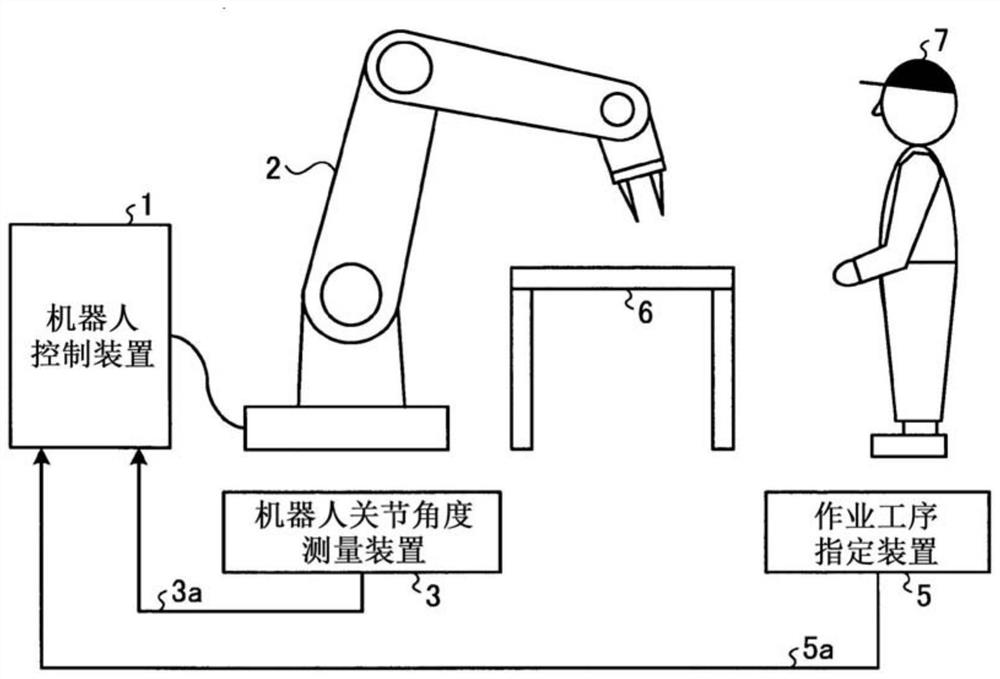
[0028] figure 1 It is a schematic diagram showing an example of a robot system including the robot control device 1 according to Embodiment 1 of the present invention and a work site to which the robot system is applied. figure 1 The robot controller 1 shown is connected to the robot 2, and outputs motion commands to the robot 2 based on the robot joint angle signal 3a from the robot joint angle measuring device 3 and the operation procedure specification signal 5a from the operation procedure specification device 5. In addition, in figure 1 In the shown work site, a workbench 6 is arranged and a worker 7 exists, and the robot 2 and the worker 7 share the work space and operate.

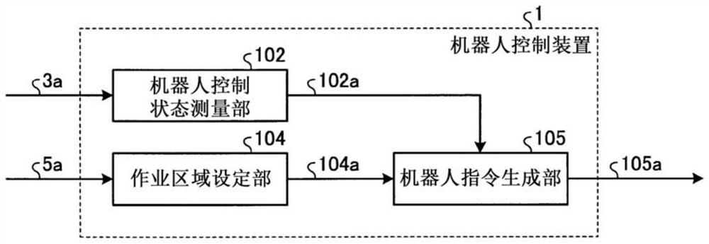
[0029] figure 2 yes means figure 1 A block diagram of a configuration example of the robot controller 1 shown. figure 2 The shown robot control device 1 has: a robot control state measurement unit 102 that measures the robot control state information 102a that is the position and posture of the...

Embodiment approach 2

[0048] In this embodiment, a mode in which the robot command generation unit in the robot controller operates to retreat the robot 2 from the work area will be described. Figure 5 It is a block diagram showing a configuration example of the robot controller 1A according to the present embodiment. Figure 5 The robot controller 1A shown replaces the figure 2 The robot command generation unit 105 shown has a robot command generation unit 105A.

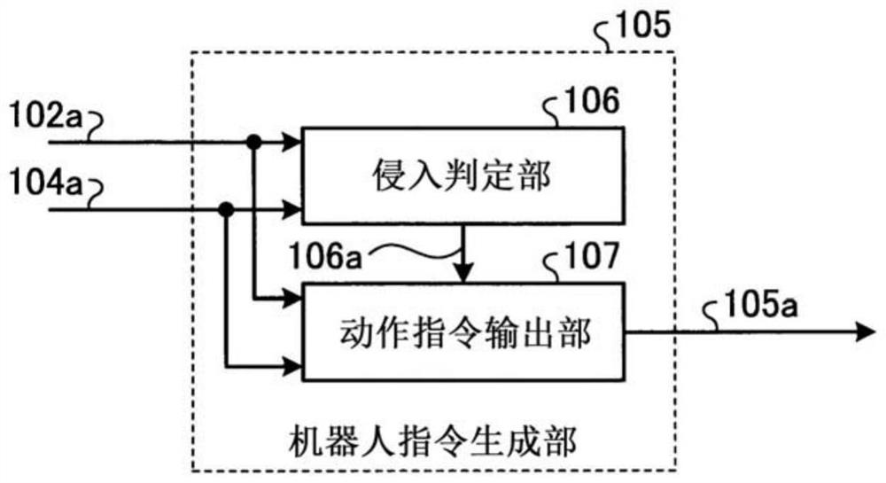
[0049] Figure 6 yes means Figure 5 A block diagram of a configuration example of the robot command generation unit 105A shown. Figure 6 The shown robot command generating unit 105A has an evasive motion trajectory generating unit 108, instead of image 3 The illustrated operation command output unit 107 has an operation command output unit 107A.

[0050] Based on the robot control state information 102a, the retraction trajectory generator 108 generates retraction trajectory information 108a ranging from the current control sta...

Embodiment approach 3

[0063] In the present embodiment, a description will be given of a mode in which the robot 2 operates so as to retreat in advance from the work area next to the current work process of the operator 7 .

[0064] Figure 8 It is a block diagram showing a configuration example of the robot controller 1B according to the present embodiment. exist Figure 8 in, right with figure 2 The structures that are the same as those shown are denoted by the same reference numerals and their descriptions are omitted. Figure 8 The Robot Controller 1B shown replaces the figure 2 The illustrated work area setting unit 104 has a work area setting unit 104B, and has a robot command generation unit 105B instead of the robot command generation unit 105 .

[0065] In the work area setting unit 104B, based on the work area in the current work process, it is stored in accordance with the order of the next work process, and in the work area information 104a corresponding to the work process of the...


PUM


Abstract

An object of the present invention is to provide a robot control device that maintains high work efficiency and reduces the possibility of collision between the operator and the robot when they share the work space and perform work. It has a robot control state measurement unit (102 ), which measures the position and posture of the robot, that is, the robot control state; the work area setting part (104), which includes the body occupied by the operator in the operation action from the beginning to the end of the operation process. The area including the space is stored for each work process, and the work area corresponding to the current work process of the operator is set based on the work process specifying signal specifying the work process currently performed by the operator; and The robot instruction generating part (105), which generates an action instruction (105a) to the robot based on the operating area and the robot control state, and the robot instruction generating part (105) responds to the action instruction (105a) of the robot according to whether the robot exists in the operating area. ) to make changes.

Description

technical field [0001] The present invention relates to a robot control device that shares a working space with humans and operates. Background technique [0002] In recent years, the development of a human-robot coordinated robot system in which a worker and a robot share a working space without being separated by a safety fence has progressed. In the human-robot coordinated robot system, the operator may intrude into the movable range of the robot. In order to prevent the collision between the two, the possibility of collision between the operator and the robot is determined based on the position and speed of the robot. In some cases, the movement of the robot is restricted in such a way that the movement of the robot is stopped, thereby ensuring safety. In addition, the closer the worker and the robot exist, or the higher the speed at which the two move, the more likely they will collide. Therefore, the movement limit of the robot should be set at a stage where both are...

Claims


Application Information

Patent Timeline
Patent Type & Authority Patents(China)
IPC IPC(8): B25J19/06B25J13/08
CPCB25J13/08B25J19/06B25J9/1676G05B2219/40G05B2219/40202G05B2219/39B25J9/1694B25J13/088
Inventor 冈原卓矢白土浩司
Owner MITSUBISHI ELECTRIC CORP
Learn More