Separation device for oil exploitation and with preliminary filter function

A separation device and preliminary technology, applied in the direction of filtration separation, purification by filtration, separation method, etc., can solve the problems of inability to filter oil initially, increased friction of oil, and increased heat, so as to facilitate inspection and adjustment, increase tightness, Easy to clean effect

Inactive Publication Date: 2019-01-08
广州科奥信息技术有限公司
View PDF8 Cites 2 Cited by
  • Summary
  • Abstract
  • Description
  • Claims
  • Application Information

AI Technical Summary

Problems solved by technology

[0004] The object of the present invention is to provide a separation device with preliminary filtration for oil development, to solve the problem that the existing separation device for oil development proposed in the above background technology is usually static, requiring the user to transfer the oil to the separation device. The inside of the device, so as to separate the oil, this separation method requires a lot of manpower and material resources to transport the oil, and the oil cannot be initially filtered during the transportation process, resulting in a long filtering time for the oil, which affects its work efficiency and causes users The filtration efficiency is low. During the transportation and filtration process, the oil is shaken by the outside world, thus forming waves and beating each other. This way, it is easy to cause the friction between the oil to increase and the heat to increase, which is likely to cause dangerous problems.

Method used


Image

  • Separation device for oil exploitation and with preliminary filter function
  • Separation device for oil exploitation and with preliminary filter function
  • Separation device for oil exploitation and with preliminary filter function

Examples


Embodiment Construction

[0026] The technical solutions in the embodiments of the present invention will be clearly and completely described below in conjunction with the accompanying drawings in the embodiments of the present invention. Obviously, the described embodiments are only a part of the embodiments of the present invention, rather than all the embodiments. Based on the embodiments of the present invention, all other embodiments obtained by those of ordinary skill in the art without creative work shall fall within the protection scope of the present invention.

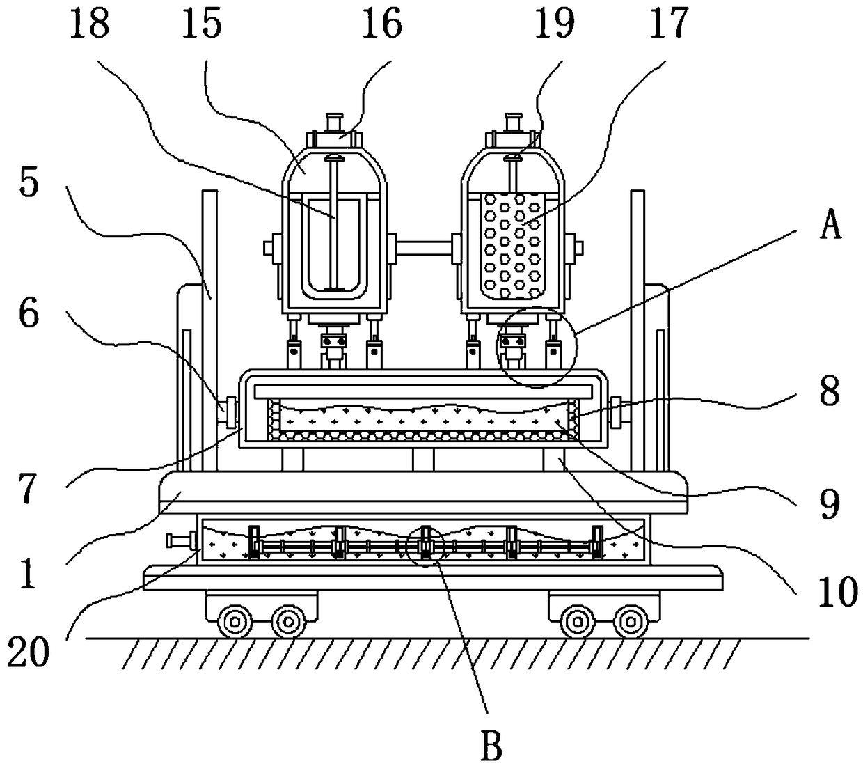
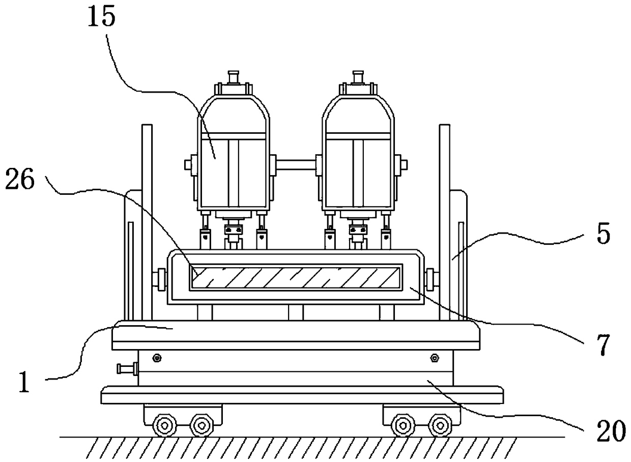
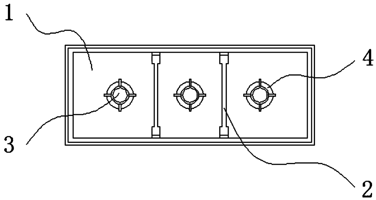
[0027] See Figure 1-5 , The present invention provides a technical solution: a separation device with preliminary filtration is used for petroleum extraction, including a connecting platform 1, a supporting rod 2, a connecting hole 3, a leak-proof pad 4, a protective fence 5, a connecting block 6, and a filter tank 7. , Filter basket 8, liquid storage chamber 9, flow pipe 10, clamping groove 11, clamping pipe 12, telescopic rod 13, exte...


PUM


Abstract

The invention relates to a separation device for oil exploitation and with a preliminary filter function. The separation device comprises a connection platform, a protection bar and liquid flow pipes,wherein a support rod is connected with the interior of the connection platform in a welding manner; connection holes are formed in the outer side of the support rod through chiseling; the outer sides of the connection holes are wrapped by leakage preventing pads; the protection bar is fastened and fixed at the upper end of the connection platform through a screw; a connection block is arranged on the inner side of the protection bar; a filter tank is connected with the inner side of the connection block through thermal welding; a filter basket is arranged in the filter tank. According to theseparation device for oil exploitation and with the preliminary filter function, the connecting holes are uniformly arrayed in a same parallel line direction with respect to the inside of the connection platform, the liquid flow pipe can be connected through the connection hole clamping bolts, and the leakage prevention pad outside the connection holes are capable of increasing the tightness therebetween so as to prevent oil from leaking during the flow process; the position of an axle wire of the filter basket is consistent with the position of an axle wire of the filter tank, so that the oil can enter the interior of the filter basket for secondary filtration.

Description

Technical field [0001] The invention relates to the technical field of petroleum exploitation, in particular to a separation device with preliminary filtration for petroleum exploitation. Background technique [0002] Oil extraction refers to the act of digging and extracting oil in places where there is oil storage. In the process of oil extraction, oil and gas flow from the reservoir to the bottom of the well, and then rise from the bottom of the well to the head of the well. The oil is deeply buried. Underground fluid minerals. Initially, people called oily liquid minerals produced in nature as petroleum, combustible gas as natural gas, and solid combustible minerals as asphalt. With the deepening of research on these minerals, they realized that they are all hydrocarbons in composition. These compounds are related to each other in cause, so they are collectively referred to as petroleum. [0003] The separation device used in the existing petroleum industry is usually static, ...

Claims


Application Information

Patent Timeline
Patent Type & Authority Applications(China)
IPC IPC(8): B01D29/56C10G31/09
CPCB01D29/56C10G31/09
Inventor 刘小英
Owner 广州科奥信息技术有限公司
Why Eureka
Try Eureka