Grinding device for welding operation

A welding machine and grinding machine technology, which is applied to grinding machines, grinding machine parts, grinding/polishing equipment, etc., can solve the problems of low production efficiency, inability to achieve continuous production, and high labor costs, and achieve high work efficiency. The effect of saving manpower and improving safety

Active Publication Date: 2019-01-08
徐州智能自动化设备有限公司
View PDF6 Cites 2 Cited by
  • Summary
  • Abstract
  • Description
  • Claims
  • Application Information

AI Technical Summary

Problems solved by technology

The current welding and grinding often need to be carried out on two devices, which cannot achieve continuous production
In most cases, both sides of the weld need to be polished, but most of the existing technologies use manual flipping, which has high labor costs and low production efficiency

Method used


Image

  • Grinding device for welding operation
  • Grinding device for welding operation
  • Grinding device for welding operation

Examples


Embodiment 1

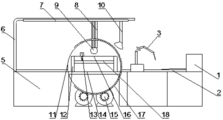
[0025] A grinding device for welding operation, comprising a plate turning machine, a welding machine is provided on one side of the plate turning machine, and a grinding machine is provided on the other side.

[0026] One side of the welding machine is provided with a welding manipulator 3, the top of the welding machine is provided with a plate track 2, and the end of the plate track 2 away from the turning machine is provided with a propeller 1, and both sides of the plate track 2 are provided with fixing clips 4 above the other end.

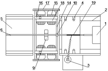
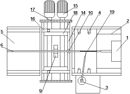
[0027] The grinding machine includes a storage table 5, on which a "┌" type frame 6 is fixed, a grinding track 7 is arranged below the crossbeam of the frame 6, and a vertically downward grinding cylinder 8 is arranged below the grinding track 7. A grinding wheel 9 is provided below the cylinder 8 . An air supply device 10 is slid on the frame 6 of the grinding machine, and the air outlet of the air supply device 10 faces the plate turning ma...

Embodiment 2

[0032] The difference from Embodiment 1 is that there are two overturning motors 15 arranged at the bottom of the turning machine, and two gears are arranged on the rotating shaft of each overturning motor 15, and the two gears are connected with the two overturning discs 11 respectively. The chain groove engagement of the two turning discs 11 can be ensured to turn over synchronously and at the same angle.


PUM


Abstract

The invention discloses a grinding device for welding operation, and belongs to the technical field of welding and grinding equipment. The grinding device comprises a plate turning machine, a weldingmachine is arranged on one side of the plate turning machine, and a grinding machine is arranged on the other side of the plate turning machine; a welding manipulator is arranged on one side of the welding machine, a plate rail is arranged at the top of the welding machine, a propeller is arranged at one end, away from the plate turning machine, of the plate rail, and fixing clamps are arranged onthe two sides of the other end of the plate rail; the plate turning machine comprises two opposite arranged turnover discs, a chain groove is formed in the peripheral surface of each turnover disc, turnover motors are arranged at the bottoms of the turnover discs, a frame beam is connected between the two turnover discs through the frame beam, and two load plates are fixed on the frame beam; andvertical columns which are vertically upward are fixed on the frame beam, two fixed beams are fixed above the vertical columns, a movable plate is fixed below the vertical columns through telescopic devices, the two ends of the movable plate are arranged in the vertical columns in a sliding mode. According to the device, the operation is simple, and welding, grinding, turning plates, polishing andcontinuous double-sided grinding operation can be realized, manual turning is not needed, manpower is saved, and the working efficiency is high.

Description

technical field [0001] The invention belongs to the technical field of welding and grinding equipment, and in particular relates to a grinding device for welding operations. Background technique [0002] In machining of mechanical parts, a weld is formed when two parts are welded together. When the two sides of the weld are welded, they will be subjected to welding heat, and the structure and performance will change. At the same time, due to the existence of welding fillers, the weld will form protrusions or burrs. To keep the weld smooth, a grinding operation is required. The current welding and grinding often need to be carried out on two devices, which cannot realize continuous production. And in most cases, both sides of the weld seam need to be polished, while most of the prior art adopts the manual flipping method, which has high labor costs and low production efficiency. [0003] Therefore develop a kind of grinding equipment that can realize welding, grinding, tur...

Claims


Application Information

Patent Timeline
Patent Type & Authority Applications(China)
IPC IPC(8): B24B27/033B24B41/00
CPCB24B27/033B24B41/00
Inventor 刘丽丽甘玉荣黄传辉戴青松
Owner 徐州智能自动化设备有限公司
Why Eureka
Try Eureka