Overhead biological chip objective table

A biochip and stage technology, applied in the field of stage, can solve the problem that the fixture stage cannot meet the processing needs, and achieve the effect of simple structure, convenient processing and production, and low processing cost

Active Publication Date: 2019-01-08
CHONGQING UNIVERSITY OF SCIENCE AND TECHNOLOGY
View PDF9 Cites 0 Cited by
  • Summary
  • Abstract
  • Description
  • Claims
  • Application Information

AI Technical Summary

Problems solved by technology

[0004] The main purpose of the present invention is to provide a biological chip positioning jig stage that meets various technological requirements such as hollow engraving of a laser engraving machine, and solve the problem that the jig stage in the prior art cannot meet the needs of process processing

Method used


Image

  • Overhead biological chip objective table
  • Overhead biological chip objective table
  • Overhead biological chip objective table

Examples


specific Embodiment 1

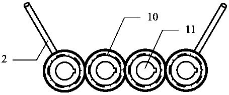
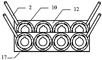
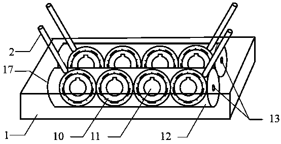
[0024] see figure 1 , Figure 7 , Figure 8 , Figure 9 , Figure 10 , Figure 11. The two columnar gears 12 are elongated columns, and the surface of the column is processed with teeth parallel to the column axis, that is, the gear shaft 13. The two columnar gears 12 are engaged with each other and installed horizontally inside the abutment 1. Inside the column gear 12 is a hollow gear with a gear hub 14 and a cavity 15 . On one side of the gear shaft 13, a row of four pinion gears 10 vertically arranged on the same space plane is installed. The space plane of the vertically arranged pinion gears 10 is parallel to the gear shaft 13 of the columnar gear 12, and two columnar gears are vertically arranged. The gears 12 mesh with each other on a horizontally placed horizontal plane. 8 small gears 10 are arranged in two rows, and one row of 4 small gears 10 is packed into a cylindrical gear 12 inside. The four chip holder rods 2 are evenly and symmetrically distributed and...

specific Embodiment 2

[0025] see Image 6 , Figure 10 . The two columnar gears 12 are elongated columns, and the surface of the column is processed with teeth parallel to the column axis, that is, the gear shaft 13. The two columnar gears 12 are engaged with each other and installed horizontally inside the abutment 1. Inside the column gear 12 is a hollow gear with a gear hub 14 and a cavity 15 . On one side of the gear shaft 13, a row of two pinion gears 10 vertically arranged on the same space plane is installed. The space plane where the vertically arranged pinion gears 10 are located is parallel to the gear shaft 13 of the columnar gear 12, and the two columnar gears are perpendicular to each other. The gears 12 mesh with each other on a horizontally placed horizontal plane. 4 small gears 10 are arranged in two rows, and 2 small gears 10 in a row are packed into a cylindrical gear 12 inside. The four chip holder rods 2 are evenly and symmetrically distributed and installed on the gear apex...

specific Embodiment 3

[0026] see figure 2 , image 3 , Figure 4 , Figure 5 . The four four-way balls 6 are arranged in the same 2 rows of even numbers vertically and horizontally, and there are two four-way balls 6 in a row. The four-way ball 6 is a sphere of the same radius that is cooperating with each other. On the vertical longitude direction surface of the four-way ball 6 spheres, the top and bottom balls of the four-way ball 6 are processed in a symmetrical cross, and the planes of the spatial direction are perpendicular to each other. A circle of longitudinal interlocking tooth lines 7 and a circle of transverse interlocking tooth lines 8. The processing of longitudinal interlocking teeth 7 and a circle of transverse interlocking teeth 8 is to ensure that when four four-way balls 6 are initially engaged together, the vertical axes of the upper and lower ball points of each four-way ball 6 remain vertical to the same horizontal plane, and the four-way balls The vertices in the directi...


PUM


Abstract

The invention provides an overhead biological chip objective table. The overhead biological chip objective table is mainly composed of a base table and a rotating device for adjusting chip rack rods.The overhead biological chip objective table is characterized in that the base table is a cuboid, the interior of the base table is machined into a hollow box shape, and the rotating device for adjusting the chip rack rods is mounted in the base table. The position, at the top of the rotating device, in the base table is connected with the chip rack rods stretching out of the base table. The rotating device is composed of four or more four-direction balls, wherein the number of the four-direction balls is an even number; or the rotating device is composed of two or more columnar gears and fouror more small gears, wherein the number of the columnar gears and the number of the small gears are both even numbers. The overhead biological chip objective table has the advantages that the machining tasks that the height is adjusted coordinately, chips of different plane sizes are elevated and clamped, and the chips are carved in a hollowed-out manner can be completed; and the structure is simple, the machining cost is low, and machining and production are facilitated.

Description

technical field [0001] The invention relates to an object stage for a fixture, in short, it is an overhead biochip stage used for processing biochips of a laser engraving machine. technical background [0002] At present, with the rapid development of integrated circuit manufacturing, micro-electromechanical systems, micro-optical devices, and biochips, fixtures that are widely used in the field of micro-processing are also emerging in an endless stream. At present, the stage of the general fixture is mostly a solid surface, and the sample to be processed is placed on the surface of the stage. However, for the special material requirements for processing biochips, it is necessary to keep the top and bottom of the processed chip to cool rapidly during the processing , or it is necessary to hollow out the chip substrate without damaging the stage, or it is necessary to quickly absorb the waste gas impurities generated by engraving from the side, etc., all of which require that...

Claims


Application Information

Patent Timeline
Patent Type & Authority Applications(China)
IPC IPC(8): B44B1/06
CPCB44B1/06
Inventor 徐文峰廖晓玲徐紫宸
Owner CHONGQING UNIVERSITY OF SCIENCE AND TECHNOLOGY
Why Eureka
Try Eureka