Automotive LED headlamp capable of conducting forced cooling during automobile motion

A technology for headlights and LED components, which is applied to motor vehicles, road vehicles, and components of lighting devices, etc., can solve the problems of high overall sealing requirements, difficult heat, and difficult sealing of headlights, so as to ensure normal performance. Work and service life, solve the sealing problem, improve the effect of heat dissipation

Active Publication Date: 2016-05-11
CHANGZHOU TONGBAO PHOTOELECTRIC MFG CO LTD
View PDF8 Cites 0 Cited by
  • Summary
  • Abstract
  • Description
  • Claims
  • Application Information

AI Technical Summary

Problems solved by technology

In order to solve the problem of LED heat dissipation, the existing technology is to install a large metal heat dissipation frame in the sealed housing of the car light, and then use a fan to force heat dissipation, which has a complex structure, high price, large volume, and difficult sealing of the car light. Solution: The overall airtightness requirements of the car lights are relatively high, and fans are used for forced heat dissipation, so the

Method used


Image

  • Automotive LED headlamp capable of conducting forced cooling during automobile motion
  • Automotive LED headlamp capable of conducting forced cooling during automobile motion
  • Automotive LED headlamp capable of conducting forced cooling during automobile motion

Examples


Embodiment 1

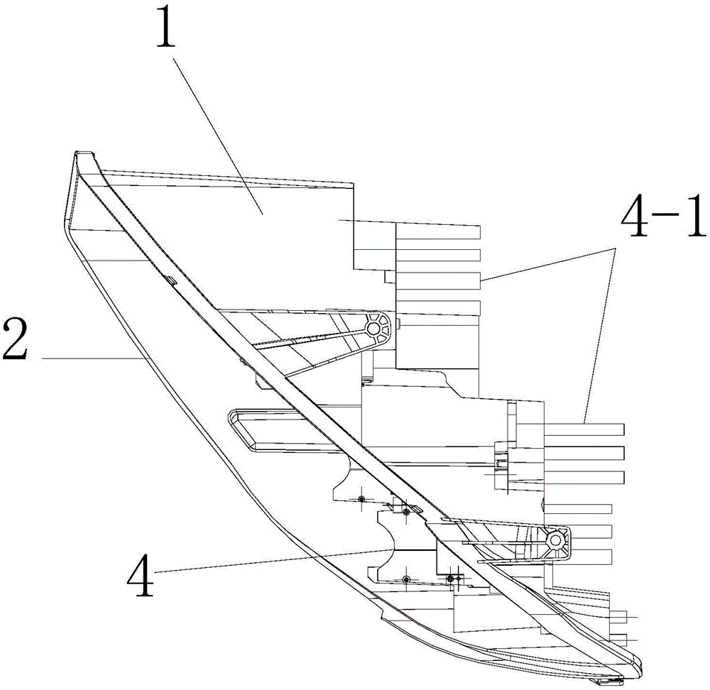
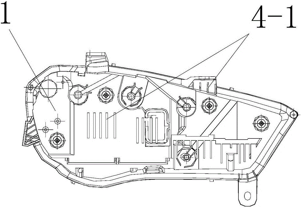
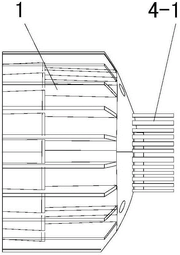
[0029] see Figure 1 to 2 ,or Figure 3-7 , The vehicle LED headlight of this embodiment includes: a heat-conducting shell 1, a transparent cover 2 sealed and arranged on the front side of the shell 1, and the shell 1 and the transparent cover 2 form a sealed cavity, in the sealed cavity An LED assembly and a metal heat dissipation frame 4 are provided. The LED assembly 3 is arranged on the metal heat dissipation frame 4. The rear end, and / or bottom, and / or top of the metal heat dissipation frame 4 extend out of the housing 1, and the metal heat dissipation frame 4 With the housing 1 hermetically fit.

[0030] The metal heat dissipation frame includes: a front panel for arranging the LED assembly 3, and the heat dissipation fins 4-1 connected to the rear side of the front panel; each heat dissipation fin 4-1 passes through the housing 1, and The middle part of each heat dissipation fin 4-1 and the casing 1 are injection-molded at one time.

[0031] When the vehicle headlight is i...

Embodiment 2

[0039] The production method of the above-mentioned vehicle LED headlight includes: fixing the metal heat dissipation frame 4 in a mold, and adopting a melting point higher than the injection temperature for the part of each heat dissipation fin 4-1 that needs to extend out of the housing 1 Fill up the gaps between adjacent radiating fins 4-1 with the materials or sheets, and then perform mold clamping, filling, pressure holding, cooling and demolding in sequence to remove the materials or sheets.


PUM


Abstract

The invention relates to an automotive LED headlamp capable of conducting forced cooling during automobile motion. The automotive LED headlamp comprises a shell and a transparent cover, a sealing cavity is formed by the shell and the transparent cover, and an LED assembly is arranged at the position, on the front side face of the shell, in the sealing cavity and arranged on a metal radiating support; and the metal radiating support extends out the shell and forms radiating fins, and the metal radiating support and the shell are in sealing fit so that heat in the automobile headlamp can be rapidly output to the exterior of the shell of the automobile headlamp through the radiating fins, and airflow generated in the automotive travelling process can conduct radiating on the radiating fins extending out of the shell. In addition, heat on the metal radiating support is transmitted to the shell through a combination part of the metal radiating support and the shell, and heat is rapidly radiated overall outwards through the shell; and meanwhile, in the automobile travelling process, the generated airflow conducts rapid air cooling on the overall shell.

Description

Technical field [0001] The invention relates to a vehicle lamp, in particular to a vehicle LED headlight and a heat dissipation method for a motor vehicle such as a car, which can be forced to air cool when the vehicle is moving. Background technique [0002] The existing domestic car lights for automobiles and other motor vehicles have begun to develop using LED as the light source. LED has the advantages of high light efficiency, long life, energy saving and environmental protection, but the current photoelectric conversion efficiency of LED is only 15%, and the remaining 85% is converted into heat energy . In order to solve the problem of LED heat dissipation, the prior art is to install a large metal heat dissipation frame in the sealed housing of the car lamp, and then use a fan for forced heat dissipation. The structure is complicated, expensive, bulky, and difficult to seal the car lamp. Solution: The overall tightness of the car lights is required to be high, and fans ar...

Claims


Application Information

Patent Timeline
IPC IPC(8): F21S8/10F21V29/76F21V29/60F21V29/87F21V29/70F21V31/00F21W101/02F21Y101/02F21W107/10
Inventor 刘威陈文祥王波陈曹杰
Owner CHANGZHOU TONGBAO PHOTOELECTRIC MFG CO LTD
Why Eureka
Try Eureka