Bearing rotary device

A rotary device and rotary disc technology, applied in rotary conveyors, transportation and packaging, conveyors, etc., can solve the problems of easy falling off of materials, low precision of rotary mechanism, etc. Effect

Pending Publication Date: 2019-01-08
HANGZHOU ZHONGWEI PHOTOELECTRICITY
View PDF11 Cites 2 Cited by
  • Summary
  • Abstract
  • Description
  • Claims
  • Application Information

AI Technical Summary

Problems solved by technology

[0004] The invention provides a load-carrying slewing device, which is used to solve the technical problem that the mat

Method used


Image

  • Bearing rotary device
  • Bearing rotary device
  • Bearing rotary device

Examples


Embodiment 1

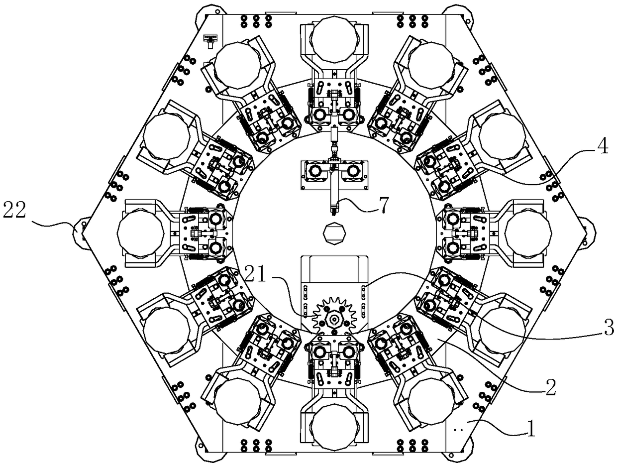
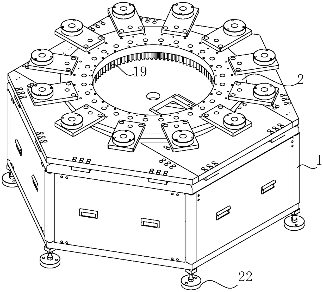
[0039] Such as figure 1 , carrying a rotary device, including a frame 1 and a rotary disc 2, the rotary disc 2 is rotatably connected to the frame 1, and a driver 3 for driving the rotary disc 2 to rotate is arranged on the frame 1, and A clamp 4 for grabbing the material to be grabbed is fixed on the rotary disk 2 .

[0040] The carrying and turning device transfers the material at a certain angle to facilitate the subsequent processing of the material. For example, the initial position of the material is at point A, and the material at point A is placed on the clamp 4 on the rotary table 2 by manual or other automatic structure and is clamped by the clamp 4. The rotary table 2 rotates at a certain angle. At this time, the material at point A The materials at point B will be moved to a new location, point B. For the subsequent processing of materials at point B, corresponding operations will be performed according to actual needs, and no specific introduction will be made he...

Embodiment 2

[0047] This embodiment is an optimization scheme for embodiment 1 in combination with embodiment 1.

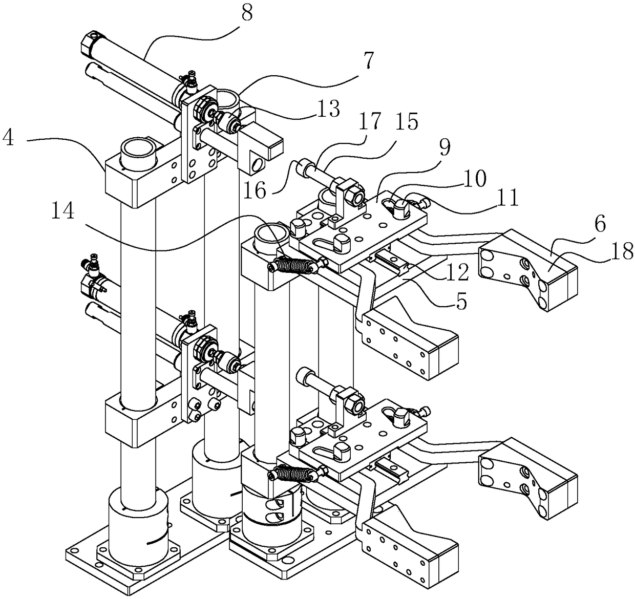
[0048] Such as image 3 A guide rail 12 is provided on the frame body 5 , and a chute matching with the guide rail 12 is provided on the slider 9 , and the guide rail 12 and the frame body 5 are integrally structured. The frame body 5 can be fixed on the frame 1 through a detachable connection.

[0049] The guide rail 12 and the chute are mainly used to improve the movement accuracy of the slider 9. The shape and arrangement of the guide rail 12 and the chute are not specifically limited, and those skilled in the art can freely choose.

Embodiment 3

[0051] This embodiment introduces the connection mode between the output device 8 and the slider 9 .

[0052] Option 1, the output device 8 includes a movable part 13 that outputs a reciprocating linear motion, and the movable part 13 resists the slider 9 and is fixedly connected with the slider 9. In this solution, the movable part 13 of the output device 8 It is fixedly connected with the slider 9, therefore, there should be a one-to-one correspondence relationship between the output device 8 and the slider 9, that is, one fixture 4 should include an independent output device 8. At this time, the output device 8 should rotate together with the rotary table 2, that is, the output device 8 should be fixed on the rotary table 2, or the output device 8 should be fixed on the structure connected with the rotary table 2, so that the output device 8 can be connected with the rotary table. Turntable 2 rotates synchronously.

[0053] Such as image 3 , or, option two, the output de...


PUM


Abstract

The invention provides a bearing rotary device. The bearing rotary device is used for solving the technical problems that materials of a rotary mechanism in the prior art are prone to falling-off, sothat the precision of the rotary mechanism is low. The bearing rotary device comprises a machine framer, a rotary disc and a driver for driving the rotary disc to rotate relative to the machine frame,clamps are arranged on the rotary disc, and the clamps comprise frame bodies, clamping arms rotationally connected to the frame bodies, sliding blocks which drive the clamping arms to open or clamp,column bodies cooperating with inclined grooves in the sliding block and output devices for driving the sliding blocks to move. The output devices drive the sliding blocks to do reciprocating motion,and clamping and loosening of the clamping arms are achieved by utilizing the cooperation between the inclined grooves and the column bodies. According to the scheme, the clamping arms can be used forclamping materials to be clamped, the clamped materials are not prone to looseness, so that the stability performance of the clamps is improved, and then the precision of the bearing rotary device isimproved; and in addition, the inclined grooves cooperate with the column bodies, so that the clamping arms are not prone to causing the movement of the sliding blocks, namely, the clamping arms hasa certain self-locking capability, and the structures of the clamps are simplified.

Description

technical field [0001] The invention relates to accessories of a material transmission system, in particular to a load-carrying rotary device, and belongs to the field of mechanical automation. Background technique [0002] The slewing mechanism is a mechanism that makes the slewing part of a crane or other machinery revolve around its slewing centerline to realize slewing motion, so as to cooperate with other mechanisms to complete the space transportation task of goods or other work cycles. The function of the slewing mechanism is to realize the plane movement of the goods, and can transport the goods to the corresponding position within the working range of the crane. [0003] The slewing mechanism has the advantages of fast action speed and high action accuracy and is widely used in the field of automation. In practical application, the slewing mechanism needs to cooperate with corresponding automatic fixtures to pick up materials. The fixture structure used in the slew...

Claims


Application Information

Patent Timeline
IPC IPC(8): B65G29/00
CPCB65G29/00
Inventor 叶欣汪辉金光前王晨洪昀
Owner HANGZHOU ZHONGWEI PHOTOELECTRICITY
Why Eureka
Try Eureka