
A filter cloth dehumidification control system

A control system and filter cloth technology, which can be used in drying gas arrangement, non-progressive dryer, lighting and heating equipment, etc., and can solve the problems of easy mold and high moisture content of filter cloth.

Active Publication Date: 2020-11-06
HANGZHOU DIANZI UNIV
View PDF6 Cites 0 Cited by
  • Summary
  • Abstract
  • Description
  • Claims
  • Application Information

AI Technical Summary

Problems solved by technology

After the filter cloth of the existing vacuum cleaner is made, there are burrs, and it needs to be followed up by the spunlace process. After the spunlace process, the moisture content of the filter cloth is too high and it is easy to mold, so the filter cloth needs to be dehumidified.

Method used


Image

  • A filter cloth dehumidification control system
  • A filter cloth dehumidification control system
  • A filter cloth dehumidification control system

Examples


Embodiment Construction

[0027] The present invention will be further described below in conjunction with the accompanying drawings of the description.

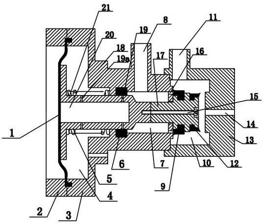
[0028] As shown in the figure, the filter cloth dehumidification control system includes a micro-control device and a filter cloth dehumidification device. The lower part of the micro-control device is equipped with a condensed water collector 26, and the lower part of the condensed water collector 26 is a condensed water collection tank 26a. The pool 26a is connected with the filter cloth dehumidification device through the condensed water collecting joint 26b. The condensed water collecting pool 26a is equipped with a floating ball 24, the floating ball 24 is equipped with a push rod 22, and the lower part of the condensed water collecting pool 26a is equipped with a sewage discharge joint 27. The joint 27 is connected with one end of the discharge pipe 28, and the other end of the discharge pipe 28 is connected with the negative pressure station 29...


PUM


Abstract

The invention relates to a dehumidification control system of filter cloth, and belongs to the technical field of condensate water treatment. The dehumidification control system comprises a micro control device and a filter cloth dehumidification device, wherein a condensate water collector is arranged on the lower part of the micro control device in a matching mode, a condensate water collectingtank is arranged on the lower part of the condensate water collector, the condensate water collecting tank is in matching connection with the filter cloth dehumidification device by virtue of a condensate water collecting joint, a floating ball is arranged on the condensate water collecting tank in the matching mode, an ejector rod is arranged on the floating ball, a pollution discharge joint is arranged on the lower part of the condensate water collecting tank in the matching mode, the pollution discharge joint is in matching connection with one end of a discharge pipe, and the other end of the discharge pipe is connected with a negative-pressure station. The dehumidification control system of the filter cloth is driven by negative pressure and has the advantages of time delay in openingand closing, controllable time, high response speed, thoroughness in discharging condensate water, difficulty in damage in a humid environment, long service life and good dehumidification effect.

Description

technical field [0001] The invention belongs to the technical field of condensed water treatment, in particular to a filter cloth dehumidification control system. Background technique [0002] Filter cloth is a filter medium made of natural fibers or synthetic fibers. It is mainly used in air filtration, dust removal, and dust collection to purify the air and protect the environment. After the filter cloth of the existing vacuum cleaner is made, there are burrs, and it needs to be followed up by the spunlace process. After the spunlace process, the moisture content of the filter cloth is too high and it is easy to mold, so the filter cloth needs to be dehumidified. . Contents of the invention [0003] In view of the above-mentioned problems existing in the prior art, the purpose of the present invention is to design and provide a technical scheme of a filter cloth dehumidification control system, which is driven by negative pressure, and its opening and closing are time-d...

Claims


Application Information

Patent Timeline
Patent Type & Authority Patents(China)
IPC IPC(8): F26B11/04F26B21/00F26B25/00
CPCF26B11/04F26B21/00F26B25/00
Inventor 许静连加俤
Owner HANGZHOU DIANZI UNIV
Learn More