A heat exchanger with a fork flushing device
A heat exchanger and fork-type technology, which is applied in the field of heat exchanger cleaning, can solve problems affecting the use of shell-and-tube heat exchangers, hindering the flow of water in the heat exchange tubes, affecting the heat exchange efficiency of the heat exchanger, etc., and achieving convenient installation , Guaranteed heat exchange effect, easy to clean effect
- Summary
- Abstract
- Description
- Claims
- Application Information
AI Technical Summary
Problems solved by technology
Method used
Image
Examples
Embodiment 1
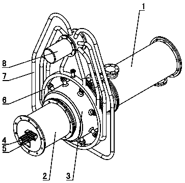
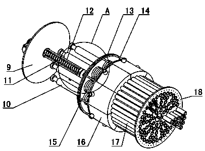
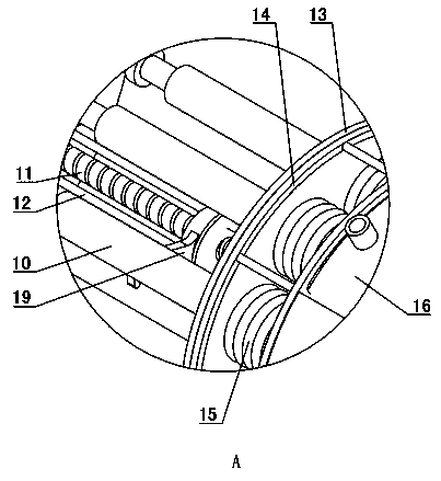
[0042] Such as Figure 1~2 As shown: the heat exchanger 1 is a cylindrical shape with both ends closed, the heat exchanger 1 is arranged horizontally, and a plurality of heat exchange tubes 101 are arranged at intervals in the heat exchanger 1, and both ends of the heat exchange tubes 101 extend out for heat exchange At the corresponding end of the heat exchanger 1, the heat exchange tube 101 is arranged parallel to the axis of the heat exchanger 1, and a plurality of fins are arranged at intervals along the axial direction in the heat exchanger 1, and the fins are semicircular, and the heat exchange tube 101 passes through The fins are fixedly connected to the heat exchanger 1, which not only facilitates the installation of the heat exchange tube 101, but also increases the heat exchange area and improves the heat exchange efficiency. Both ends of the heat exchanger 1 are coaxially provided with flanges.
[0043] The left end of the heat exchanger 1 is coaxially equipped wit...
Embodiment 2
[0056] Such as Figure 8~11 As shown, the difference between Embodiment 2 and Embodiment 1 is that the heat exchange tubes 101 in the heat exchanger 1 are arranged in multiple rows at intervals, and each row is arranged with a plurality of heat exchange tubes 101 at intervals along the radial direction of the heat exchanger 1 . The transition cylinder 3 is only provided with a distribution plate 21, and a plurality of flushing pipes 17 are arranged on the distribution plate 21. The flushing pipes 17 are arranged at the end of the distribution plate 21 close to the heat exchanger 1, and the number of the flushing pipes 17 is the same as that contained in each column. The number of heat exchange tubes 101 is equal, and the distance between each flushing tube 17 and the center of the distribution plate 21 is equal to the distance between the corresponding heat exchange tubes 101 in each row and the center of the heat exchanger 1 . The side of the distribution plate 21 is provide...
PUM
 Abstract
Description
Claims
Application Information
 - R&D
- Intellectual Property
- Life Sciences
- Materials
- Tech Scout
- Unparalleled Data Quality
- Higher Quality Content
- 60% Fewer Hallucinations
Browse by: Latest US Patents, China's latest patents, Technical Efficacy Thesaurus, Application Domain, Technology Topic, Popular Technical Reports.
© 2025 PatSnap. All rights reserved.Legal|Privacy policy|Modern Slavery Act Transparency Statement|Sitemap|About US| Contact US: help@patsnap.com


