A laser light source and a laser projection system

A laser light source and laser technology, applied in the field of optics, can solve the problems of not meeting the development requirements of lasers, high cost, complex optical structure, etc.

Pending Publication Date: 2019-01-08
QINGDAO HISENSE LASER DISPLAY CO LTD
View PDF14 Cites 2 Cited by
  • Summary
  • Abstract
  • Description
  • Claims
  • Application Information

AI Technical Summary

Problems solved by technology

[0004] The structure of the above-mentioned laser projection system needs to set a lens for each monochromatic laser light path, the cost

Method used


Image

  • A laser light source and a laser projection system
  • A laser light source and a laser projection system
  • A laser light source and a laser projection system

Examples


Embodiment 1

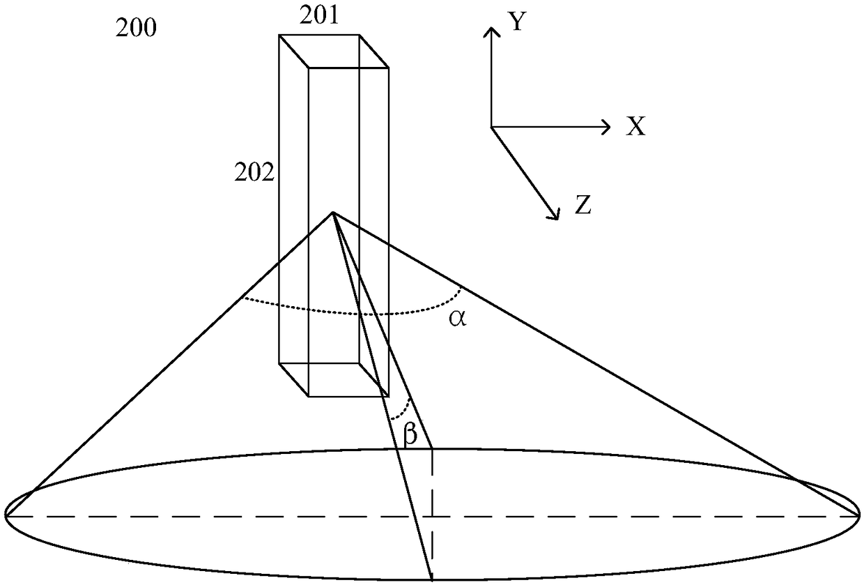
[0063] The laser exit is rectangular with an aspect ratio of 16:10. The DMD light valve has a rectangular shape with an aspect ratio of 16:9. The entrance and exit of the light rod are both rectangular, with the side parallel to the X axis as the horizontal side and the side parallel to the Y axis as the vertical side. The aspect ratio of the light bar entrance is 9:16, and the aspect ratio of the exit port is 16:9.

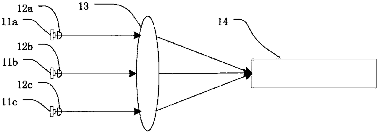
[0064] In the first embodiment, since the size of the entrance of the light rod does not completely correspond to the size of the exit of the laser, the light beam emitted from the laser cannot be collected efficiently.

Embodiment 2

[0066] The laser exit is rectangular with an aspect ratio of 16:10. The DMD light valve has a rectangular shape with an aspect ratio of 16:9. Both the entrance and exit of the light rod are rectangular, the aspect ratio of the entrance is 10:16, and the aspect ratio of the exit is 16:10. The length of the light rod is 20+ / -0.2mm.

[0067] In the second embodiment, due to the short length of the light rod, the uniform light effect is not optimal. At the same time, the size of the exit port does not exactly match the DMD, so the beam cannot be used efficiently.

Embodiment 3

[0069] The laser exit is rectangular with an aspect ratio of 16:10. The DMD light valve has a rectangular shape with an aspect ratio of 16:9. Both the entrance and exit of the light rod are rectangular, the aspect ratio of the entrance is 10:16, and the aspect ratio of the exit is 16:9. The length of the light rod is 35+ / -0.2mm.

[0070] If the optical rod is a hollow barrel structure, specifically, the inner diameter of the entrance is 6.8+ / -0.1mm×4.2+ / -0.1mm, and the outer diameter is 9+ / -0.2mm×6.4+ / -0.2mm; the size of the inner diameter of the exit port is 3.5+ / -0.1mm×5.6+ / -0.1mm, and the size of the outer diameter is 5.35+ / -0.2mm×7.8+ / -0.2mm.

[0071] In embodiment three, the size of each part of the light rod matches the existing optical device, that is, the entrance of the light rod matches the size of the laser exit port, and the exit port of the light rod matches the light valve of the DMD, so that the difference in beam divergence angle is obtained Optimization, t...


PUM

PropertyMeasurementUnit
Lengthaaaaaaaaaa

Abstract

The invention relates to the field of optical technology, in particular to a laser light source and a laser projection system, which are used for simplifying the optical path system and satisfying therequirement of miniaturization of a laser. The laser light source provided by the embodiment of the invention comprises a laser and an optical rod connected with the laser, and an entrance port of the optical rod is connected with an exit port of the laser. A length of a first side of a first cross section of the light rod at an entrance opening of the light rod is greater than a length of a second side of the first cross section at an exit opening of the light rod, the first cross section of the light rod being perpendicular to an entrance opening of the light rod and parallel to a fast axisdirection; And/or a length of a third side of a second cross section of the light rod at an entrance opening of the light rod is greater than a length of a fourth side of the second cross section atan exit opening of the light rod, the second cross section of the light rod being perpendicular to an entrance opening of the light rod and parallel to a slow axis direction.

Description

technical field [0001] The invention relates to the field of optical technology, in particular to a laser light source and a laser projection system. Background technique [0002] Laser display projection technology is an emerging projection display technology that is developing rapidly. Its outstanding features are high brightness, large color gamut, and low cost. At present, the two-color laser technology is mature, but the three-color laser is still in the research and development stage. How to further improve the brightness and color performance and make the laser more integrated is a problem being studied at this stage. [0003] Due to the great difference between the fast axis and the slow axis of the semiconductor laser, that is, the divergence angles of the light beam emitted by the laser are different on the fast axis and the slow axis. Among them, the divergence angle of the beam emitted by the laser is the largest in the direction of the fast axis, and the diverg...

Claims


Application Information

Patent Timeline
IPC IPC(8): G03B21/20
CPCG03B21/2033G03B21/208
Inventor 周子楠田有良李巍孙鹏
Owner QINGDAO HISENSE LASER DISPLAY CO LTD
Why Eureka
Try Eureka