
Integrated luminous identification

A technology for luminous signs and light sources, applied in the field of signs, can solve the problems of discount of overall visual effect, poor light absorption, lack of beauty and texture, etc., and achieve the effect of simple and convenient light source setting, reducing workload and difficulty

Pending Publication Date: 2019-01-08
马飞
View PDF4 Cites 0 Cited by
  • Summary
  • Abstract
  • Description
  • Claims
  • Application Information

AI Technical Summary

Problems solved by technology

First of all, this kind of luminous sign is only suitable for dark environments, such as the "exit" sign of a movie theater, because the transparent plate and the engraved pattern on it have poor light absorption, and the engraved pattern can only emit light weakly compared to the transparent plate itself. Visual lack of beauty and texture
Secondly, this kind of luminous sign is only suitable when all patterns emit one light color
Finally, due to the transmission of light in the transparent board, if there are stains or scratches on the surface of the transparent board, it will be quite obvious, which will greatly reduce the overall visual effect

Method used


Image

  • Integrated luminous identification
  • Integrated luminous identification
  • Integrated luminous identification

Examples


Embodiment 1

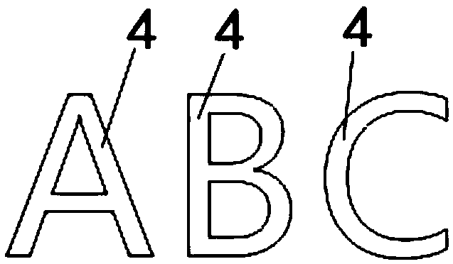
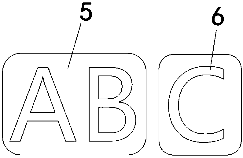
[0075] like Figure 1A-Figure 1F As shown, this embodiment intends to provide an integrated light-emitting sign. The light-emitting sign is a character pattern displaying "ABC", which is divided into two parts "AB" and "C" according to the plan, and each part corresponds to a set of light sources. In this way, the "AB" character pattern can be distinguished from "C" in light color and brightness effect. This embodiment includes: a plate-shaped base, that is, a substrate 1 , a panel 2 , an LED strip light source 3 , a light-transmitting member 4 and a light guide plate 5 . Wherein, the LED strip light source 3 is a plurality of patch LED light sources welded on a circuit board, and the circuit board is a flexible circuit board and / or a hard circuit board.

[0076] The substrate 1 plays the role of carrying the panel 2 , the light guide plate 5 and the light source 3 .

[0077] Two mounting grooves 12 are provided on the base plate 1. The mounting grooves 12 here belong to a b...

Embodiment 2

[0086] like Figure 2A-Figure 2D As shown, this embodiment intends to provide an integrated light-emitting sign, the light-emitting sign is a character pattern displaying "ABC", and is divided into three parts "A", "B" and "C" according to the plan, and each part corresponds to A set of light sources, so that the character patterns of "A" and "B" and "C" can be set with different light colors and brightness. This embodiment includes: a plate-shaped base, that is, a substrate 1 , a panel 2 , an LED strip light source 3 , a light-transmitting member 4 and a light guide plate 5 .

[0087] The differences between this embodiment and Embodiment 1 are: 1. The three mounting grooves 12 of the substrate 1 are through-groove structures, the upper grooves of the mounting grooves 12 cover the panel 2, and the lower grooves are provided with a light-shielding and reflective base plate 8; 2. , the fronts of the three light guide plates 5 are respectively provided with hollow out grooves 9...

Embodiment 3

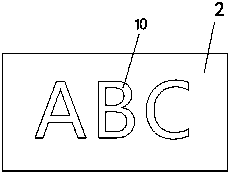
[0090] like Figure 3A-Figure 3D As shown, this embodiment intends to provide an integrated light-emitting sign, the light-emitting sign is a character pattern displaying "ABC", and "ABC" corresponds to a set of light sources, so that the light color and brightness of the three character patterns can be guaranteed to be consistent. This embodiment includes: a plate-shaped base, that is, a substrate 1 , a panel 2 , an LED strip light source 3 , a light-transmitting member 4 and a light guide plate 5 .

[0091] This embodiment differs from the above embodiments in that: 1, the installation groove 12 on the substrate 1 is a through groove structure without a bottom plate; 2, the three character pattern engraved grooves 6 are arranged on the back side of the light guide plate 5 (on the light guide plate 5 The side away from the panel), the back notch of the hollow groove 10 on the panel 2 is docked at the corresponding position on the front of the light guide plate 5, and this pos...


PUM


Abstract

An integrated luminous identification is provided, in accordance with that present invention. The integrated luminous identification includes a base, a light guide plate, a panel and a light-transmitting member. The base is provided with a mounting groove for receiving a light guide plate and a light source. The light guide plate is provided with an astigmatism mark. The panel is provided with a hollow groove. The light emitted from the light source enters the light guide plate through the cross section of the light guide plate and is irradiated on the astigmatism mark transversely, and the light emitted from the astigmatism mark is emitted through the light transmitting member butted with the hollow groove and emitted out of the panel. A light source correspond to that light transmittingpart can be flexibly arrange in the scheme, the light transmitting parts of the same kind are centralized correspond to the same light source by classifying the light emitting requirements of the light transmitting parts, different lights do not interfere with each other, and the distribution and the setting process and the workload of the light source in the manufacturing process of the traditional light emitting mark are greatly simplified. At the same time, the special structure enables the scheme to make a more elaborate small-size luminescent logo.

Description

technical field [0001] The invention relates to the field of identification plates, in particular to an integrated luminous identification. Background technique [0002] Most of the existing advertising luminous signs are box structures, which are composed of a base plate, an LED light source fixed on the base plate, a surrounding edge and a light-transmitting cover plate. Each complete luminous logo is composed of several independent small patterns or strokes, and each independent small pattern or stroke is an independent light box, each light box must be equipped with a light source, and finally put all the small patterns or The strokes are combined according to the corresponding coordinate positions to form the final pattern, and then the power supplies of all the light boxes are connected together. Such a structure is made, and it is time-consuming to waste work and waste materials, and the procedure is loaded down with trivial details. If you want to make a small-size...

Claims


Application Information

Patent Timeline
Patent Type & Authority Applications(China)
IPC IPC(8): G09F13/18
CPCG09F13/04G09F13/0404G09F13/10G09F13/18G09F13/22G02B6/0021G02B6/0038G09F2013/1859G09F2013/184G09F2013/222G09F2013/1836G09F13/0418
Inventor 不公告发明人
Owner 马飞
Learn More