
Matrix-type socket

A matrix and socket technology, applied in contact parts, electrical components, coupling devices, etc., can solve the problems of complex structure and high cost, and achieve the effect of solving radial tolerance, reducing production cost and simple structure

Pending Publication Date: 2019-01-08
WUTONG HLDG GRP CO LTD
View PDF0 Cites 0 Cited by
  • Summary
  • Abstract
  • Description
  • Claims
  • Application Information

AI Technical Summary

Problems solved by technology

From the hardware point of view, this requires 64 channel antennas to be connected to the RF front-end devices respectively. At this time, the connection between the antenna and the RF front-end becomes an important factor that limits the integration of the product.
[0003] The traditional solution is to use one-to-one fixed connection, which requires the connector to be made into a movable device to ensure system tolerance. This connection method is complex in structure and high in cost

Method used


Image

  • Matrix-type socket
  • Matrix-type socket

Examples


Embodiment 1

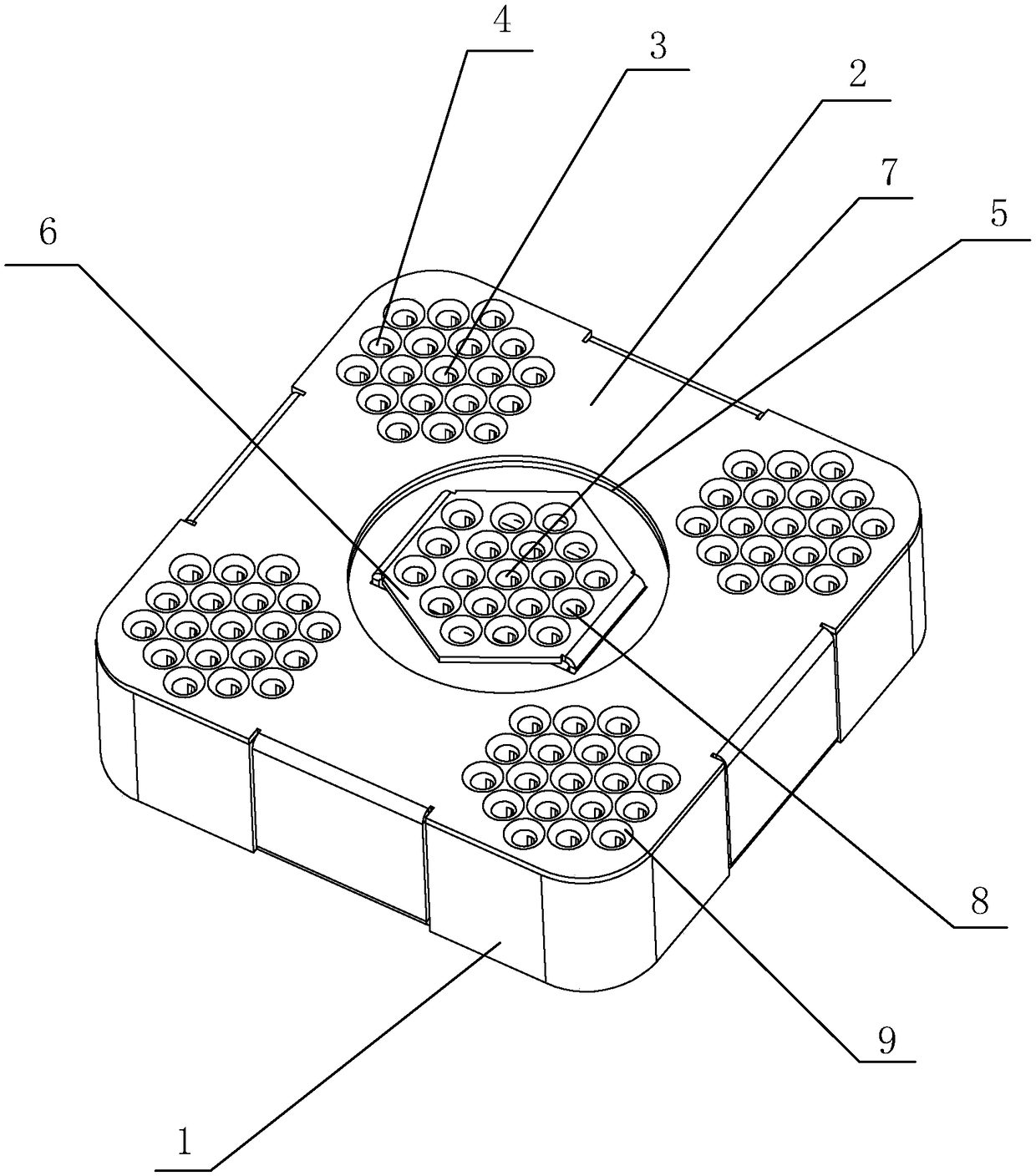
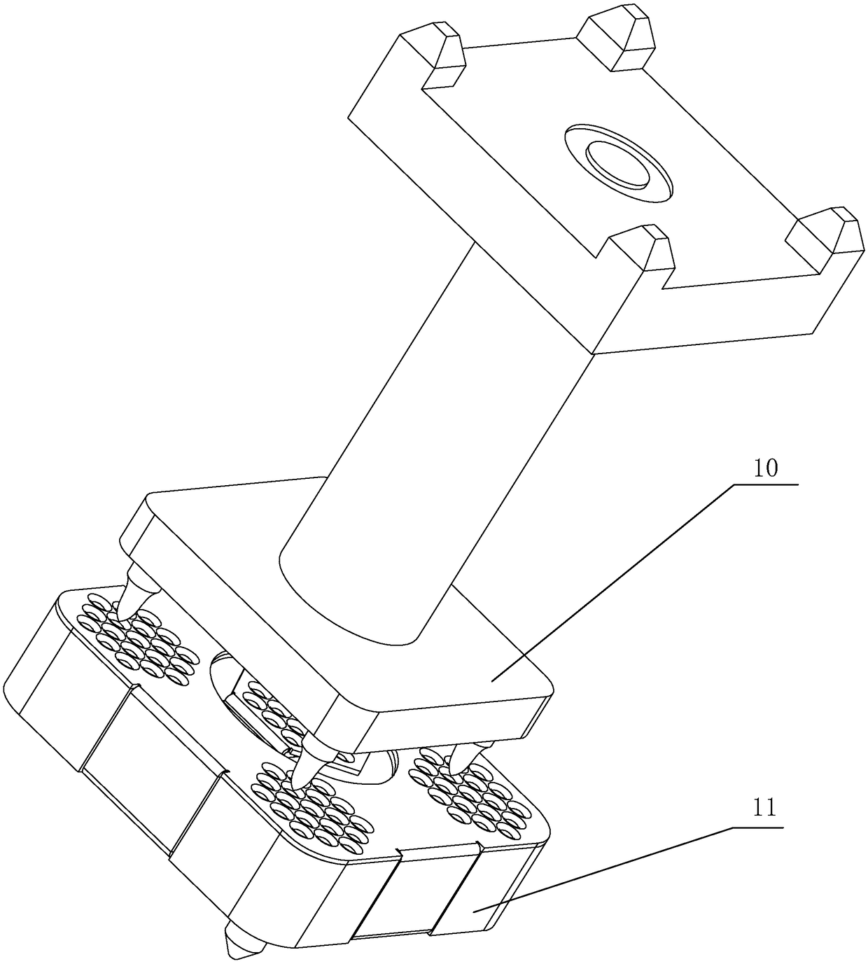
[0020] Embodiment one: see Figure 1~2 As shown, a matrix socket includes a body 11, one end of the body 11 is welded on the PCB main board, and the other end is electrically connected to a multi-pin radio frequency plug 10, the body 11 includes a base 1 and a grounding reed 2, The grounding reed 2 is snap-connected to the base 1, and several groups of jack components are arranged on the grounding reed 2, and the positions of the jack components are adapted to the positions of the multi-pin radio frequency plug 10, each A group of jack components includes a plurality of conductive connecting holes, and one end of the conductive connecting holes in the same group is connected in parallel to the output end of the group of jack components. The product has simple structure and convenient connection, and the production cost of the product is greatly reduced.

[0021] see figure 1 As shown, a conductive connection hole in each group of the jack assembly is set as the central conne...


PUM


Abstract

A matrix type socket is disclose, include a body, one end of the body is soldered on the PCB main board, the other end is electrically connected with a multi-pin radio frequency plug, characterized inthat: the body comprises a base and a grounding spring, the grounding reed clasp is connected with the base, A plurality of groups of jack assemblies are arranged on the grounding spring, the positions of the jack assemblies are corresponding to the positions of the multi-pin radio frequency plugs, each group of the jack assemblies comprises a plurality of conductive connection holes, and one endof the conductive connection holes in the same group is connected in parallel with the output end of the group of jack assemblies. The product has the advantages of simple structure and convenient connection, solves the problem of radial tolerance of the original product, ensures that at least one set of jacks can be connected with a multi-pin radio frequency plug, and improves the electric performance and intermodulation performance of the product.

Description

technical field [0001] The invention relates to the field of wireless communication, in particular to a matrix socket. Background technique [0002] As communication enters the 5G era, base station equipment is gradually developing towards large-scale array antennas and integration. The channel signal is processed, so as to realize the function of the system with digital multi-wave speed. From a hardware point of view, this requires 64 channel antennas to be connected to the RF front-end devices respectively. At this time, the connection between the antenna and the RF front-end becomes an important factor that limits the integration of the product. [0003] The traditional solution is to use a one-to-one fixed connection, which requires the connector to be made into a movable device to ensure system tolerance. This connection method is complex in structure and high in cost. Therefore, how to solve the above problems is the direction that engineers need to study at this sta...

Claims


Application Information

Patent Timeline
IPC IPC(8): H01R13/10H01R13/629H01R13/631H01R13/652H01R25/00
CPCH01R13/10H01R13/629H01R13/631H01R13/652H01R25/00
Inventor 黄克猛沈细荣陈伟
Owner WUTONG HLDG GRP CO LTD
Learn More