A tubular combined surgical robot

A surgical robot and combined technology, applied in surgical manipulators, surgical robots, surgery, etc., can solve the problems of waste of expenses and resources, inability to use flexible endoscope surgery and interventional surgery, etc., and achieve easy maintenance, portability, assembly, and debugging. simple effect

Pending Publication Date: 2019-01-11
SIHONG ZHENGXING MEDICAL TECH CO LTD
View PDF3 Cites 2 Cited by
  • Summary
  • Abstract
  • Description
  • Claims
  • Application Information

AI Technical Summary

Problems solved by technology

However, the above-mentioned equipment cannot be used universally in soft mirror surgery and interventional surgery, forcing the hospital to purchase two kinds of equipment, resulting in additional expenses and waste of resources

Method used


Image

  • A tubular combined surgical robot
  • A tubular combined surgical robot
  • A tubular combined surgical robot

Examples


Embodiment 1

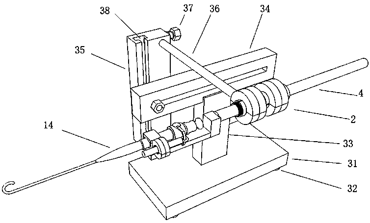
[0048] The structure of the tubular combined surgical robot of the present invention is as follows: figure 1 As shown, the supporting device moves to the side of the operating table and fixes the rollers 32. Adjust the positions of the horizontal support bar 34 , the vertical support bar 35 and the longitudinal support bar 36 to a suitable position, and fix it in the sliding groove 38 with a fixing nut 37 . The surgical robot includes an instrument fixture 4 and a driving base 2, and the driving base 2 is connected and fixed with a longitudinal support rod 36.

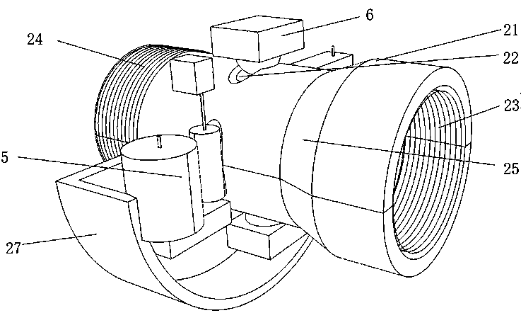
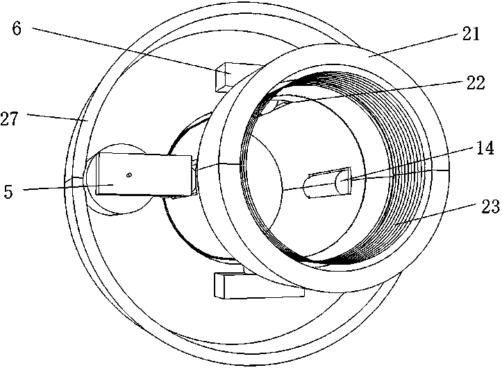
[0049] Such as figure 2 As shown, the driving assembly 5 and the induction assembly 6 are installed in the driving seat housing 27, and all of them are fixed by a fixed card seat. This is a channel tube for driving the instrument fixture 4 to advance or retreat along the inner wall of the channel tube 21 , and is referred to as the advance and retreat channel tube for short in the following. The driving directions of...

Embodiment 2

[0069] This example Figure 10 What is shown is a simplification based on the first embodiment. This embodiment is used for interventional operations, and the improvement is that the catheter holder 15 is clamped on the holder 11, and the toggle device 7 in the first embodiment is omitted. The conduit holder is a pipeline, and the conduit 17 is fixed by the adjustment knob 16 after being inserted. Other structures of the surgical robot are the same as those of Embodiment 1. The control device of the surgical robot in this embodiment is basically the same as that in Embodiment 1, except that the manual dial 82 is omitted.

Embodiment 3

[0071] Such as Figure 11 As shown, the structure of this embodiment is similar to that of Embodiment 1, the difference is that the rotation drive base and the advance and retreat drive base are not directly connected. The advance and retreat driving seat is connected with the longitudinal support rod 36, and there is a strip-shaped longitudinal limiter 43 on the instrument fixing part 4, and there is a gap matching it on the passage tube. Such as Figure 12 As shown, the longitudinal limiting member 43 restricts the instrument fixing member 4 to only move forward or backward in the channel tube 21 . One end of the instrument fixing part 4 is provided with a circular limiter 44, which limits the rotation of the driving seat to only rotate between the circular limiter 44 and the tapered pipe neck of the channel pipe. One end of the L-shaped rod 42 is connected to the shell of the rotating drive seat, and the other end is connected to the holder 11 .


PUM


Abstract

The invention provides a tubular combined surgical robot, which comprises an instrument fixing member, a channel tube and a driving assembly. An instrument fixture passes through the channel tube, andthe channel tube engages with the drive assembly; the channel tube may be used in combination with another channel tube through axial connection. The invention also provides a control device based onthe same structural principle. The invention axially connects the channel tubes with different driving functions, simplifies the structure of the surgical robot and the control device, and increasesthe mobility of the surgical robot in a narrow space. The control device and the execution device of the invention have the same structure, have the tactile feedback to the operator, improve the portability and the operability of the surgical robot, and are common for the soft mirror robot surgery and the intervention robot surgery.

Description

technical field [0001] The invention relates to a surgical robot system, in particular to a tubular combined surgical robot. Background technique [0002] At present, the da Vinci robot is the most successful minimally invasive robot commercialized and clinically used in the world. The open-loop parallelogram telecentric positioning mechanism adopted by the robot relies on the synchronous constraints of the steel belt to realize the parallelogram mechanism. The disadvantage of this mechanism is that When assembling, it is necessary to find the telecentric positioning point with the help of the device. The passive arm is integrated with a mechanical arm based on a mobile platform. The disadvantage of this method is that the entire mechanical system is bulky. In order to facilitate preoperative adjustment, the passive arm needs to have four degrees of freedom, resulting in a longer cantilever beam, which reduces the overall rigidity of the robot. At the same time, due to the ...

Claims


Application Information

Patent Timeline
IPC IPC(8): A61B34/37A61B17/00
CPCA61B34/30A61B17/00234A61B34/70A61B34/73A61B34/74A61B34/76A61B2034/302A61B2034/742
Inventor 郑杨郑兴
Owner SIHONG ZHENGXING MEDICAL TECH CO LTD
Why Eureka
Try Eureka