Eureka AIR delivers breakthrough ideas for toughest innovation challenges, trusted by R&D personnel around the world.

Non-stick pan inner coating production line

A production line, non-stick pan technology, applied in spraying devices, spray booths, etc., can solve the problems of wasting space, low production efficiency, long beginning and end of the assembly line, etc., to ensure spraying quality, improve production efficiency, and improve cooling effect. Effect

Pending Publication Date: 2019-01-11
YANCHENG FEIYALI MACHINERY
View PDF0 Cites 2 Cited by
  • Summary
  • Abstract
  • Description
  • Claims
  • Application Information

AI Technical Summary

Problems solved by technology

[0002] Now whether it is an electric rice cooker or a pressure cooker, it is necessary to spray paint on the inside and outside of the pot, and the inside of the pot needs to be sprayed with a primer, a middle paint and a top coat in sequence. Paint spraying room, primer drying room, primer cooling room, intermediate paint spraying room, intermediate paint drying room, intermediate paint cooling room and finish paint spraying room, the circulation chain arranged in a straight line passes through the primer spraying room, The primer drying room, the primer cooling room, the intermediate paint spraying room, the intermediate paint drying room, the intermediate paint cooling room and the finish paint spraying room are used for painting operations. This kind of setting is firstly a waste of space, and secondly, the beginning and end of the assembly line It is relatively long, it is not convenient for maintenance personnel to inspect and maintain equipment, the production efficiency is relatively low and the cooling effect during the painting process
Not good, which will affect the quality of subsequent paint spraying

Method used


Image

  • Non-stick pan inner coating production line
  • Non-stick pan inner coating production line
  • Non-stick pan inner coating production line

Examples


Embodiment Construction

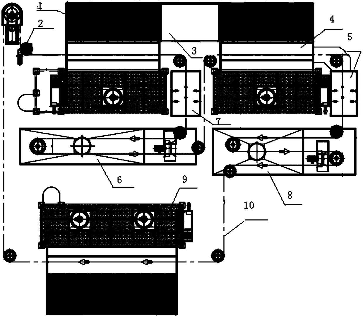
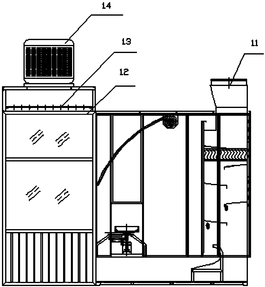
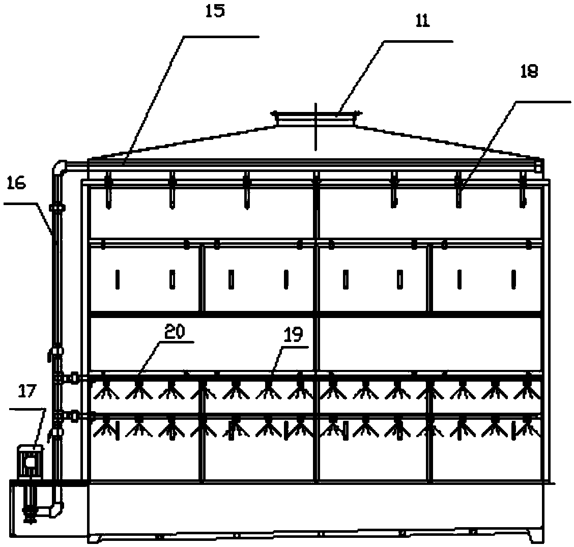
[0015] Non-stick pan internal coating production line, which includes a paint spraying device, a drying device, a cooling device and a circulation chain 10. The paint spraying device includes a paint mixing room 3, a primer spraying room 1, a medium paint spraying room 4 and a topcoat spraying room 9 , the drying device includes a first drying device 7 and a second drying device 5, the cooling device includes a first cooling device 6 and a second cooling device 8, and the primer spray booth and the middle paint spray booth are arranged side by side Set, the paint mixing room is located at the rear between the primer spray booth and the intermediate paint spray booth, the first drying device is located at the front between the primer spray booth and the intermediate paint spray booth, and the first The cooling device is located in front of the primer spray booth and the first drying device, the second drying device is located on the right side of the intermediate paint spray boo...


PUM


Abstract

The invention relates to the technical field of non-stick pan production, in particular to a non-stick pan inner coating production line. The non-stick pan inner coating production line comprises a paint spraying device, drying devices, cooling devices and a circulation chain. A paint mixing room and the first drying device are both located between a primer spraying room and an intermediate coat spraying room; the first cooling device is located in front of the primer spraying room and the first drying device; the second drying device is located on the right side of the intermediate coat spraying room; the second cooling device is located in front of the intermediate coat spraying room and the second drying device; a finishing coat spraying room is located in front of the first cooling device; and the circulation chain sequentially passes through the primer spraying room, the first drying device, the first cooling device, the intermediate coat spraying room, the second drying device, the second cooling device and the finishing coat spraying room to be arranged in the first cooling device and the second cooling device in a multiple surrounding mode. According to the non-stick pan inner coating production line, the space is saved, maintenance personnel conveniently inspect and repair equipment, the production efficiency is high, the cooling effect can be guaranteed, and the coating spraying quality is improved.

Description

technical field [0001] The invention relates to the technical field of non-stick pan production, in particular to a non-stick pan inner coating production line. Background technique [0002] Now whether it is an electric rice cooker or a pressure cooker, it is necessary to spray paint on the inside and outside of the pot, and the inside of the pot needs to be sprayed with a primer, a middle paint and a top coat in sequence. Paint spraying room, primer drying room, primer cooling room, intermediate paint spraying room, intermediate paint drying room, intermediate paint cooling room and finish paint spraying room, the circulation chain arranged in a straight line passes through the primer spraying room, The primer drying room, the primer cooling room, the intermediate paint spraying room, the intermediate paint drying room, the intermediate paint cooling room and the finish paint spraying room are used for painting operations. This kind of setting is firstly a waste of space, ...

Claims


Application Information

Patent Timeline
IPC IPC(8): B05B16/20B05B13/06B05B16/60B05B14/465
CPCB05B13/06B05B14/465B05B16/20B05B16/60
Inventor 王亚王建刚
Owner YANCHENG FEIYALI MACHINERY
Why Eureka
Eureka Blog
Learn More