Automatic feeding and discharging necking machine for steel pipes

An automatic feeding and shrinking technology, applied in metal processing equipment, feeding devices, stripping devices, etc., can solve the problems of increasing labor costs, high labor intensity, and large volume, reducing labor intensity and improving work efficiency. , the effect of accurate positioning

Inactive Publication Date: 2019-01-11
WUHU YUANMA AUTOMATION EQUIP CO LTD
View PDF5 Cites 3 Cited by
  • Summary
  • Abstract
  • Description
  • Claims
  • Application Information

AI Technical Summary

Problems solved by technology

[0002] In the machinery industry, necking is required in many places, and the diameter of the mouth of the workpiece is reduced to the same size as the outer diameter of the assembled part before assembly. The existing necking machines are mainly operated manually by manpower, and workers are required in the process of processing. Put the steel pipes into the shrinking machine one by one, the steel pipes are heavy and bulky, resulting in low production efficiency, high labor intensity, and increased labor costs

Method used


Image

  • Automatic feeding and discharging necking machine for steel pipes
  • Automatic feeding and discharging necking machine for steel pipes

Examples


Embodiment Construction

[0014] In order to deepen the understanding of the present invention, the present invention will be further described below in conjunction with examples, which are only used to explain the present invention and do not constitute a limitation to the protection scope of the present invention.

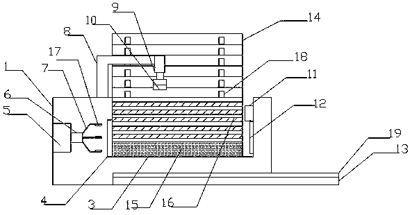
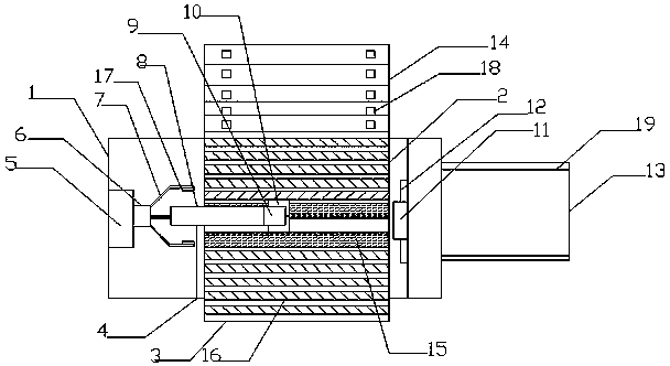
[0015] Such as Figure 1-2 As shown, this embodiment provides a steel pipe automatic loading and unloading shrinking machine, including a base 1, a fixed support plate 2 is provided on the left side of the middle of the base 1, and a movable support plate 3 is provided on the right side of the middle of the base 1. The fixed support plate 2 and the movable support plate 3 are set in a V shape, the left end of the movable support plate 3 is provided with a horizontal slide rail 4, the movable support plate 3 is connected with the base 1 through the slide rail 4, and the left end of the base 1 is provided with a rotating motor 5. The front end of the rotary motor 5 is provided with a telesc...


PUM


Abstract

The invention provides an automatic feeding and discharging necking machine for steel pipes. The automatic feeding and discharging necking machine comprises a machine base. A fixed support plate is arranged on the left side in the middle of the machine base. A movable support plate is arranged on the right side in the middle of the machine base. The fixed support plate and the movable support plate are arranged in a V-shape. A transverse sliding rail is arranged at the left end of the movable support plate. The movable support plate is connected with the machine base through the sliding rail.A rotating motor is arranged at the left end in the machine base. A telescopic rod is arranged at the front end of the rotating motor. A gripper is arranged at the front end of the telescopic rod. A support seat is arranged above the left end of the machine base. A telescopic cylinder is arranged at the front end of the support seat. A fixed clamping hand is arranged at the lower end of the telescopic cylinder. The fixed clamping hand is positioned above the joint of the fixed support plate and the movable support plate. A necking disc and a rotating disc are arranged at the right end of the machine base. The rotating disc is arranged at the lower end of the necking disc. A discharging conveyor belt is arranged at the bottom end of the machine base. A feeding conveyor belt is arranged on the left side of the fixed support plate. The automatic feeding and discharging necking machine effectively improves the working efficiency and reduces the labor intensity.

Description

technical field [0001] The invention relates to the field of mechanical processing, in particular to an automatic loading and unloading necking machine for steel pipes. Background technique [0002] In the machinery industry, necking is required in many places, and the diameter of the mouth of the workpiece is reduced to the same size as the outer diameter of the assembled part before assembly. The existing necking machines are mainly operated manually by manpower, and workers are required in the process of processing. Putting the steel pipes into the shrinking machine one by one, the steel pipes are heavy and bulky, resulting in low production efficiency, high labor intensity, and increased labor costs. Therefore, it becomes very important to solve the problems of low production efficiency and high labor intensity. Contents of the invention [0003] The object of the present invention is to provide a steel pipe automatic loading and unloading necking machine, the steel p...

Claims


Application Information

Patent Timeline
Patent Type & Authority Applications(China)
IPC IPC(8): B21D41/04B21D43/12B21D43/00B21D45/00
CPCB21D41/04B21D43/003B21D43/006B21D43/12B21D45/00
Inventor 胡世珍
Owner WUHU YUANMA AUTOMATION EQUIP CO LTD
Why Eureka
Try Eureka