Standing operation stud welding device
A technology for welding devices and studs, which is applied in the direction of supporting electrode clamps, welding equipment, welding accessories, etc., to achieve the effects of small footprint, significant progress, industrial practical value, and accurate positioning
- Summary
- Abstract
- Description
- Claims
- Application Information
AI Technical Summary
Problems solved by technology
Method used
Image

Examples
Embodiment 1
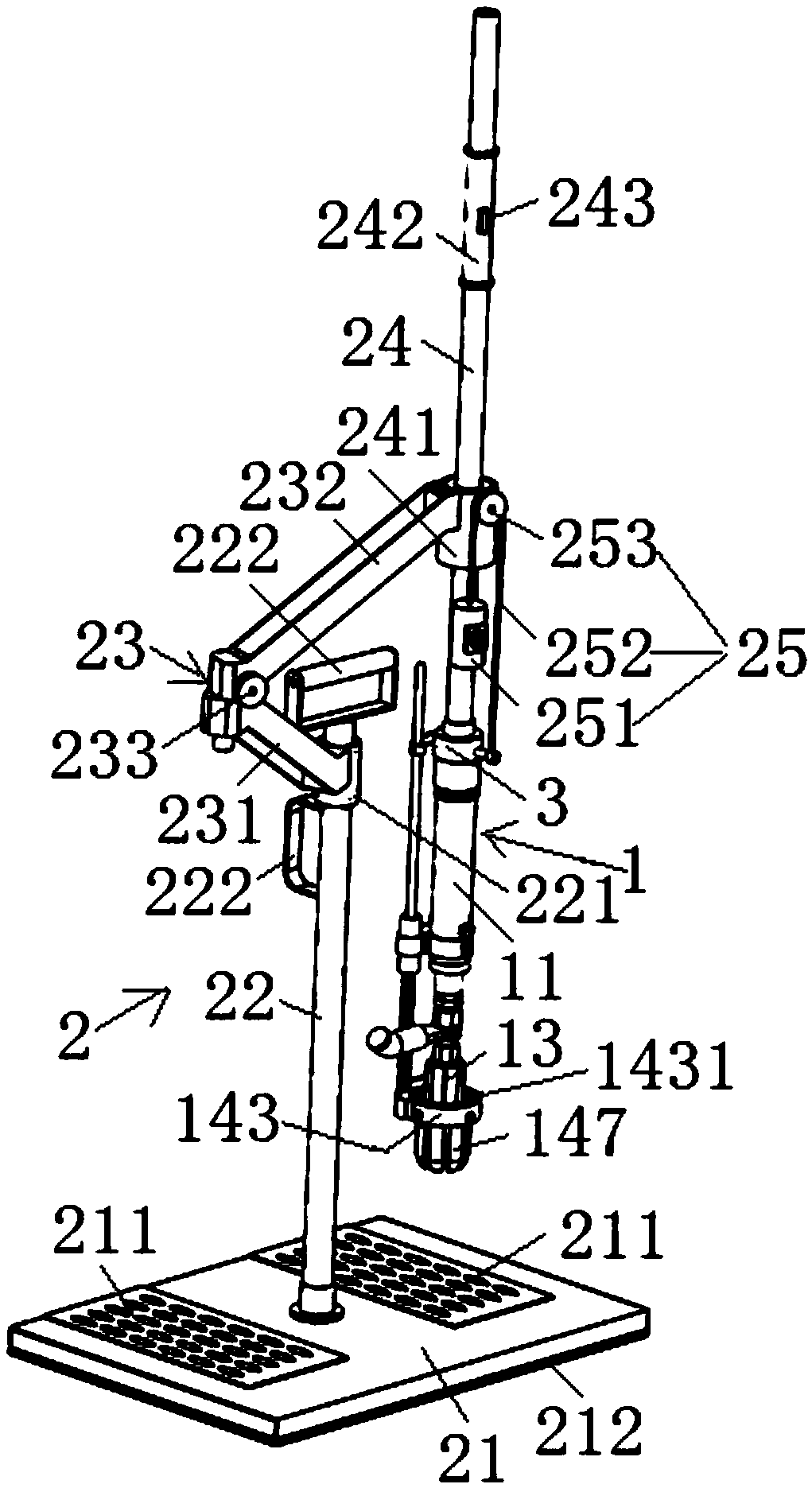
[0029] Such as figure 1 As shown: a stud welding device for standing operation provided in this embodiment, including a welding torch 1 and a standing auxiliary platform 2, the standing auxiliary platform 2 includes a base 21, a column 22, a 360-degree horizontal rotating arm 23, and a lifting rod 24 And the balance mechanism 25, the column 22 is fixed at the center position of the base 21, the 360-degree horizontal rotating arm 23 is composed of an A arm 231 and a B arm 232, wherein: one end of the A arm 231 is arranged on the column 22 The bearing A 221 on the top is fixedly connected, the other end of the A arm 231 is connected with one end of the B arm 232 through a pin shaft 233, and the other end of the B arm 232 is fixedly connected with the bearing B 241 arranged on the elevating rod 24, and the bearing B 241 can slide up and down on the elevating rod 24; the welding torch 1 is fixedly connected to the bottom end of the elevating rod 24 through the connecting seat 3, a...
Embodiment 2
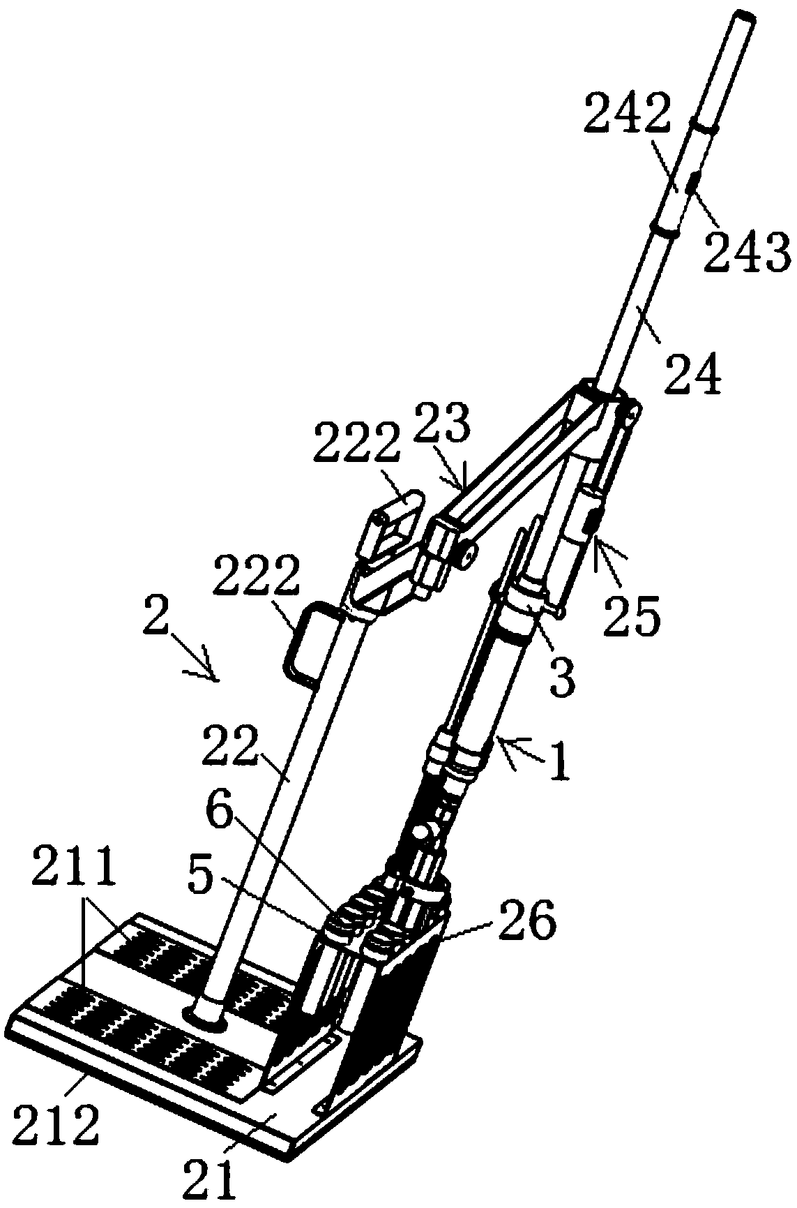
[0036] Such as image 3 As shown: a stud welding device for standing operation provided in this embodiment, the only difference from Embodiment 1 is that the standing auxiliary platform 2 also includes a nail rack 26, and the nail rack 26 is fixed on On the base 21, by manually placing a plurality of studs to be welded on the nail rack 26, the automatic feeding of the stored studs can be realized, which can further improve welding efficiency and convenience.
[0037] The usage method of the stud welding device described in the present embodiment is as follows:
[0038] First, the welding torch 1 is fixed on the lower end of the elevating rod 24 by the connecting seat 3, and then the whole device is shifted to the vicinity of the workpiece 4 to be welded by hand (see Figure 4 to Figure 6 shown);
[0039] Secondly, the operator stands on the base 21, then holds the hand-held portion 242 of the elevating rod 24, and makes the welding gun 1 be positioned at the sleeve to be cla...
Embodiment 3
[0043] see Figure 7 As shown: the upper side of each welding nail position on the nail rack 26 provided in this embodiment is fixed with a nail-taking limit card 261, and the nail-taking limit card 261 is an arc with an opening facing outward. The opening size of the arc is adapted to the outer circumference of the ceramic ring chuck 147, so that the ceramic ring chuck 147 can be limited in the arc, so that the welding torch can be quickly positioned to the nail-taking position, and the nail-taking can be ensured. Accuracy and speed of operation. The staple removal limiter 261 can be fixed at a suitable height through the fixing column 262 , and the suitable height means that it can form an enclosing relationship with the upper part of the ceramic ring chuck 147 . In addition, the nail setting frame 26 may not be fixed on the base 21, as long as it is placed within the nail picking range of the welding torch.
PUM
 Abstract
Description
Claims
Application Information
 - R&D
- Intellectual Property
- Life Sciences
- Materials
- Tech Scout
- Unparalleled Data Quality
- Higher Quality Content
- 60% Fewer Hallucinations
Browse by: Latest US Patents, China's latest patents, Technical Efficacy Thesaurus, Application Domain, Technology Topic, Popular Technical Reports.
© 2025 PatSnap. All rights reserved.Legal|Privacy policy|Modern Slavery Act Transparency Statement|Sitemap|About US| Contact US: help@patsnap.com