Binding clamp with cutting function

A technology of cutting function and pliers, which is applied in the direction of shearing device, wire tensioning equipment, hand-held metal shearing equipment, etc. It can solve the problems of cumbersome operation process, difficult to tighten the iron wire, and poor control of the length of the wire head. To achieve the effect of simplifying the workflow, saving operation time, and simple and smooth operation

Active Publication Date: 2019-01-11
蔡盼
View PDF6 Cites 2 Cited by
  • Summary
  • Abstract
  • Description
  • Claims
  • Application Information

AI Technical Summary

Problems solved by technology

During the bundling operation, it is difficult to tighten the iron wire, and the operation process is cumbersome, and af

Method used


Image

  • Binding clamp with cutting function
  • Binding clamp with cutting function
  • Binding clamp with cutting function

Examples


Example Embodiment

[0033] In order to make the objectives, technical solutions and advantages of the present invention clearer, the following further describes the present invention in detail with reference to the accompanying drawings and embodiments. It should be understood that the specific embodiments described herein are only used to explain the present invention, but not to limit the present invention.

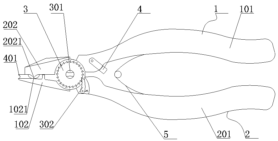
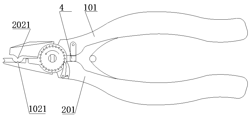
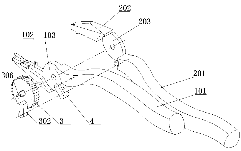
[0034] For gas pipes, water pipes and other pipes, when hoses are connected to metal pipes and other hard pipes, in order to ensure air tightness and prevent the joints from loosening, it is necessary to use clamps to fasten the joints, but it is common to use iron wires to make hoops for fastening. Of operation. When using iron wire to tie hoop, such as Figure 8 As shown, the iron wire is first made into a hoop preparation 6 which includes a bend 603, an end A601, and an end B602. The end A601 and the end B602 are placed inside the bend 603. Put the band clamp 6 on the outside of the hose...


PUM


Abstract

The invention relates to a binding clamp with a cutting function. The binding clamp comprises a first clamp body and a second clamp body, a jackscrew table is arranged in the middle of a first jaw, and wire placing grooves are formed in the two sides of the jackscrew table. A groove is formed in the top end of the jackscrew table, and a ratchet wheel is installed on the outer side of the first jaw. A pawl is installed on the second clamp body, and the pawl is matched with the ratchet wheel. When the binding clamp with the cutting function is used in occasions such as tightening of a hose and ahard pipe joint, a clamp handle is repeatedly pressed, then iron wires can be tightened, and the tightening aim is achieved. After tightening, the iron wires can be cut off through an upper knife edge and a lower knife edge on the jaw, the operation is simple and smooth, the operation time is saved, the work process is simplified, and the aims of improving the working efficiency of the binding operation and improving the working quality are achieved.

Description

technical field [0001] The invention relates to the field of hardware tools, in particular to a clamp clamp with a cutting function. Background technique [0002] In the fields of construction, industry, agriculture, etc., it is often necessary to connect hoses and hard pipes, or to bundle thin and long items. When using iron wire to tie hoops, operators often use tools such as vise to bind. During the binding operation, it is difficult to tighten the iron wire, and the operation process is relatively cumbersome during tightening, and after binding, the iron wire needs to be cut off with pliers, and the length of the left iron wire head is not easy to control. Contents of the invention [0003] In order to overcome the deficiencies in the prior art, the present invention provides a clamp pliers with cutting function. The invention is used to collect iron wire clamps, and is convenient to cut off excess iron wires after tightening. The operation is time consuming. [000...

Claims


Application Information

Patent Timeline
IPC IPC(8): B25B25/00B23D29/02
CPCB23D29/023B25B25/00
Inventor 不公告发明人
Owner 蔡盼
Why Eureka
Try Eureka