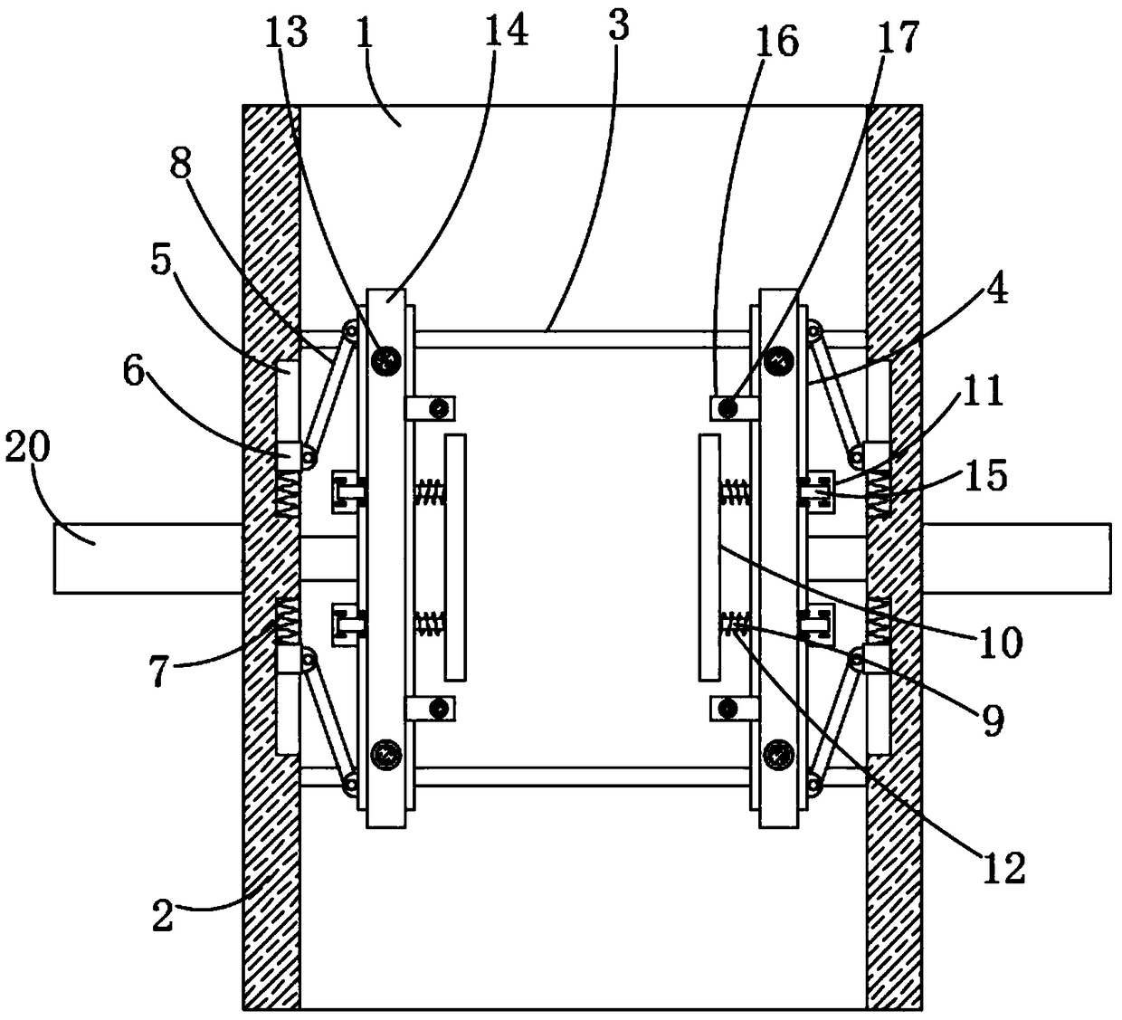
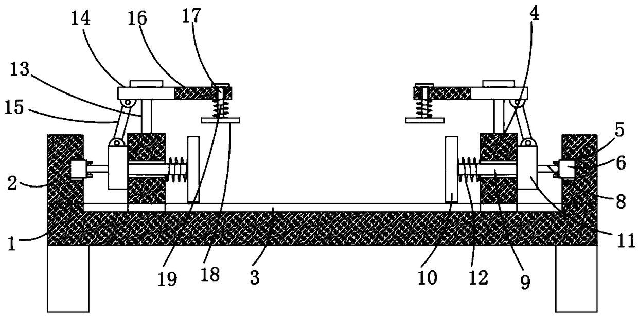
Plate engraving machine fixing device

A fixing device and engraving machine technology, applied in the field of plate processing, can solve the problems of high labor intensity, large amount of labor, and low production efficiency, and achieve the effects of improving processing efficiency, ensuring processing quality, and ensuring stability

Inactive Publication Date: 2019-01-11
黄雨辰
View PDF0 Cites 5 Cited by
  • Summary
  • Abstract
  • Description
  • Claims
  • Application Information

AI Technical Summary

Problems solved by technology

[0002] Plate decoration has a very wide range of applications in the construction field. The processing of decorative plates is mostly manual carving, which is labor-intensive, requires a large amount of labor, and has low production efficiency. It cannot be mass-produced and cannot adapt to the huge market demand. , and the quality of manual carving cannot be guaranteed. Even two works carved by the same worker cannot achieve the exact same quality.
[0003] At present, various board engraving machines have appeared on the market, which can reduce the labor intensity of workers, but the existing board engraving machines usually fix the wood boards manually, which makes the efficiency low and manual operation It cannot ensure that the plate is fixed enough, so we design a plate engraving machine fixing device to solve the above problems

Method used


Image

  • Plate engraving machine fixing device
  • Plate engraving machine fixing device
  • Plate engraving machine fixing device

Examples


Embodiment Construction

[0019] The following will clearly and completely describe the technical solutions in the embodiments of the present invention with reference to the accompanying drawings in the embodiments of the present invention. Obviously, the described embodiments are only some, not all, embodiments of the present invention.

[0020] In describing the present invention, it should be understood that the terms "center", "longitudinal", "transverse", "length", "width", "thickness", "upper", "lower", "front", " Orientation indicated by rear, left, right, vertical, horizontal, top, bottom, inside, outside, clockwise, counterclockwise, etc. The positional relationship is based on the orientation or positional relationship shown in the drawings, and is only for the convenience of describing the present invention and simplifying the description, rather than indicating or implying that the referred device or element must have a specific orientation, be constructed and operated in a specific orientat...


PUM


Abstract

The invention belongs to the field of plate machining, and particularly discloses a plate engraving machine fixing device. The plate engraving machine fixing device comprises a workbench, side platesare symmetrically and fixedly connected to the two sides, in the length direction of the workbench, of the top side of the workbench, and sliding grooves are symmetrically formed in the portions, located between the two side plates, of the top side of the workbench; movable plates are symmetrically and slidably installed between the two sliding grooves, and driving mechanisms are connected to thesides, far away from each other, of the two movable plates; and clamping grooves are symmetrically formed in the sides, close to each other and located between the two sliding grooves, of the two sideplates, clamping blocks are slidably installed in the clamping grooves, and first springs are installed on the sides, close to each other, of the two clamping blocks in the two clamping grooves. According to the plate engraving machine fixing device, through the structural design of the movable plates, the clamping grooves, the clamping blocks, the first springs, supporting rods, connecting rods,clamping plates, connecting blocks, second springs, fixing rods and pushing rod motors, the top side edge of a plate can be extruded and fixed while the side wall of the plate is extruded and fixed.

Description

technical field [0001] The invention relates to the technical field of plate processing, in particular to a plate engraving machine fixing device. Background technique [0002] Plate decoration has a very wide range of applications in the construction field. The processing of decorative plates is mostly manual carving, which is labor-intensive, requires a large amount of labor, and has low production efficiency. It cannot be mass-produced and cannot adapt to the huge market demand. , and the quality of manual carving cannot be guaranteed. Even two works carved by the same worker cannot achieve exactly the same quality. [0003] At present, various board engraving machines have appeared on the market, which can reduce the labor intensity of workers, but the existing board engraving machines usually fix the wood boards manually, which makes the efficiency low and manual operation It cannot ensure that the plate is fixed enough, so we have designed a plate engraving machine fi...

Claims


Application Information

Patent Timeline
Patent Type & Authority Applications(China)
IPC IPC(8): B44B3/06B44B1/06
CPCB44B3/065B44B1/06
Inventor 周国旗
Owner 黄雨辰
Why Eureka
Try Eureka