A method for assembling upper and lower interior walls and floor slabs

An assembly method and an interior wall technology, which are applied in the direction of construction and building construction, can solve the problems of lack of effective detection means for the density of grouting materials, waste of steel reinforcement materials, and high cost of grouting materials, so as to avoid the difficulty of effective detection of grouting quality and avoid Difficult installation and reduced wet work

Active Publication Date: 2021-10-12
绿建科技集团新型建材高技术有限公司
View PDF5 Cites 0 Cited by
  • Summary
  • Abstract
  • Description
  • Claims
  • Application Information

AI Technical Summary

Problems solved by technology

[0003] In the prior art, the above-mentioned connecting nodes have the following main problems during construction: 1. When the shear wall is hoisted, the steel bars protruding from the bottom are easy to collide and bend, and manual calibration and adjustment are required in the later stage, and the construction efficiency is low; 2. The top of the shear wall The accuracy of the protruding steel bars reserved on the side is difficult to achieve accurately, and the situation of cutting the reserved protruding steel bars during construction often occurs, resulting in waste of steel bar materials and affecting the quality of the project, and it is time-consuming and labor-intensive to accurately align the steel bars and sleeves , it is prone to serious misalignment that leads to the failure of installation, which seriously affects the construction period and construction cost; 3. The grouting quality of sleeve grouting varies, and the grouting density is difficult to uniform and strictly control, and the grouting material density at the grouting anchor connection joint lacks effective detection method, the cost of grouting materials is high, and the cleaning of grouting equipment is time-consuming and complicated; 4. The height of the mortar joints between the shear walls cannot be accurately controlled, and the density and strength are greatly reduced compared with the prefabricated shear wall components, which is an earthquake-resistant weak zone; 5. 1. The cleaning of grouting equipment is time-consuming and complicated; 6. The quality of the slurry is high and the cost is high; 7. The labor cost is high, the construction time is long, and the construction quality is difficult to control

Method used


Image

  • A method for assembling upper and lower interior walls and floor slabs
  • A method for assembling upper and lower interior walls and floor slabs
  • A method for assembling upper and lower interior walls and floor slabs

Examples


Embodiment 1

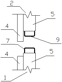
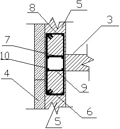
[0071] see figure 1 and figure 2 As shown, the assembly nodes of the exterior wall shear wall and the floor slab in this embodiment include the first shear wall 1 , the second shear wall 2 and the floor slab 3 . Both the first shear wall 1 and the second shear wall 2 include an outer thermal insulation layer 4 and an inner load-bearing layer 5 connected as one, and the bottom side of the thermal insulation layer 4 is longer than the load-bearing layer 5, and the top side is lower than the load-bearing layer 5; the load-bearing layer 5 is provided with steel mesh (not drawn among the figure). The top side and the bottom side of the load-bearing layer 5 are provided with prefabricated connecting beams, and connecting steel bars are arranged in the prefabricated connecting beams. In this embodiment, the connecting steel bars are stirrups; The beam 6 is provided with a first stirrup 7; the bottom side of the load-bearing layer 5 of the second shear wall 2 is a second prefabrica...

Embodiment 2

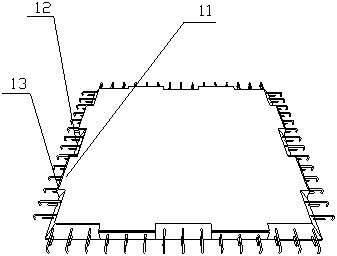
[0078] refer to Figure 5 As shown, the assembly nodes of the exterior wall shear wall and the floor slab in this embodiment include the first shear wall 1, the second shear wall 2 and the floor 3, and the first shear wall 1 and the second shear wall 2 are both Including insulation layer 4 and load-bearing layer 5; insulation layer 4 and load-bearing layer 5 are connected into one body, insulation layer 4 is a fiber cement insulation board, the two sides are wider than load-bearing layer 5, the lower part is longer than load-bearing layer 5, and the upper part is lower than load-bearing layer 5 . The load-bearing layer 5 is provided with a double-sided steel mesh (not marked in the figure), and the double-sided steel mesh is formed by cross-connecting longitudinal rectangular steel rings and vertical rectangular steel rings 14 .

[0079] see Figure 4 The vertical section of the external wall shear wall shows the distribution of vertical rectangular reinforcement rings in the ...

Embodiment 3

[0087] Such as Figure 4 , Figure 7 , Figure 8 As shown, the assembly nodes of the exterior wall shear wall and the floor slab in this embodiment include the first shear wall 1, the second shear wall 2 and the floor slab 3, and the structure of the connection node is roughly the same as that in the second embodiment, the specific difference is that the vertical The positions of the reinforcing bars 10 are different, and the specific description is as follows:

[0088] see Figure 7 As shown, in this embodiment, the longitudinal steel bar 10 is arranged inside the rectangular steel bar anchor ring 15 and is close to the surface of the load-bearing layer 5, that is, the rectangular steel bar protruding from the top side of the load-bearing layer 5 of the first shear wall 1 In the anchor ring 15, two first longitudinal steel bars 19 are arranged close to the surface of the load-bearing layer 5, and in the rectangular reinforcement anchor ring 15 protruding from the bottom si...


PUM


Abstract

The invention provides a method for assembling upper and lower inner walls and floors, comprising the following steps: S1, prefabrication of inner wall shear walls and floor slabs; S2, hoisting and installation: hoisting and positioning the first inner wall shear wall, hoisting the second The first floor and the second floor are respectively placed on the two ends of the top side of the first interior wall shear wall, and then the second interior wall shear wall is hoisted and placed on the top side of the first interior wall shear wall, and the second interior wall shear wall The two ends of the bottom side are respectively pressed on the supporting ribs on the top side of the first floor and the second floor; cavities are formed between the floor and the shear wall of the first interior wall and the shear wall of the second interior wall. Set up longitudinal steel bars, tie bars and anchors; S3, pouring connection: pouring concrete into the cavity to form double-lapped post-casting beams or double-anchored horizontal post-casting strips to connect the floor slab and the interior wall shear wall into one. The on-site construction amount of the connection node is small, the cost is reduced, the construction period is saved, and the integrity and seismic strength of the building are greatly improved.

Description

technical field [0001] The invention belongs to the technical field of prefabricated buildings, and in particular relates to a method for assembling upper and lower inner walls and floor slabs. Background technique [0002] In the prior art, the main form of the connection node between the shear wall and the floor is: the upper and lower shear walls are connected through a grouting sleeve, the laminated floor is placed on the top side of the shear wall, and the laminated floor is poured after placing the longitudinal reinforcement. The cast-in-place layer of the floor slab forms a whole with the laminated floor slab and the shear wall. [0003] In the prior art, the above-mentioned connecting nodes have the following main problems during construction: 1. When the shear wall is hoisted, the steel bars protruding from the bottom are easy to collide and bend, and manual calibration and adjustment are required in the later stage, and the construction efficiency is low; 2. The to...

Claims


Application Information

Patent Timeline
Patent Type & Authority Patents(China)
IPC IPC(8): E04B1/04
CPCE04B1/04E04B1/046
Inventor 谢向荣李浩沈鸣谢怀宇谢向阳赵万选
Owner 绿建科技集团新型建材高技术有限公司
Why Eureka
Try Eureka