Natural gas engine combustion organization method adopting manifold multiple-injection, pre-combustion chamber low-pressure gas supply and diesel oil micro-jetting ignition

A technology of multiple injection and pre-combustion chamber, which is applied to combustion engines, internal combustion piston engines, engine components, etc., can solve the problems of unreasonable organization of stratified combustion, stable ignition research, lean mixture misfire and knocking, and slow flame propagation speed and other problems, to achieve the effect of improving misfire and knocking problems, improving combustion quality, improving economy and emission

Active Publication Date: 2019-01-11
HARBIN ENG UNIV
View PDF12 Cites 8 Cited by
  • Summary
  • Abstract
  • Description
  • Claims
  • Application Information

AI Technical Summary

Problems solved by technology

[0004] In order to make better use of the emission advantages of natural gas, natural gas engines usually work under a leaner mixture, but the main component of natural gas, methane, has a higher ignition point, slower flame propagation speed and longer combustion duration during the combustion process, which is easy to produce Large cycle fluctuations, lean mixtures are also prone to misfire and knocking. In order

Method used


Image

  • Natural gas engine combustion organization method adopting manifold multiple-injection, pre-combustion chamber low-pressure gas supply and diesel oil micro-jetting ignition
  • Natural gas engine combustion organization method adopting manifold multiple-injection, pre-combustion chamber low-pressure gas supply and diesel oil micro-jetting ignition
  • Natural gas engine combustion organization method adopting manifold multiple-injection, pre-combustion chamber low-pressure gas supply and diesel oil micro-jetting ignition

Examples


Embodiment Construction

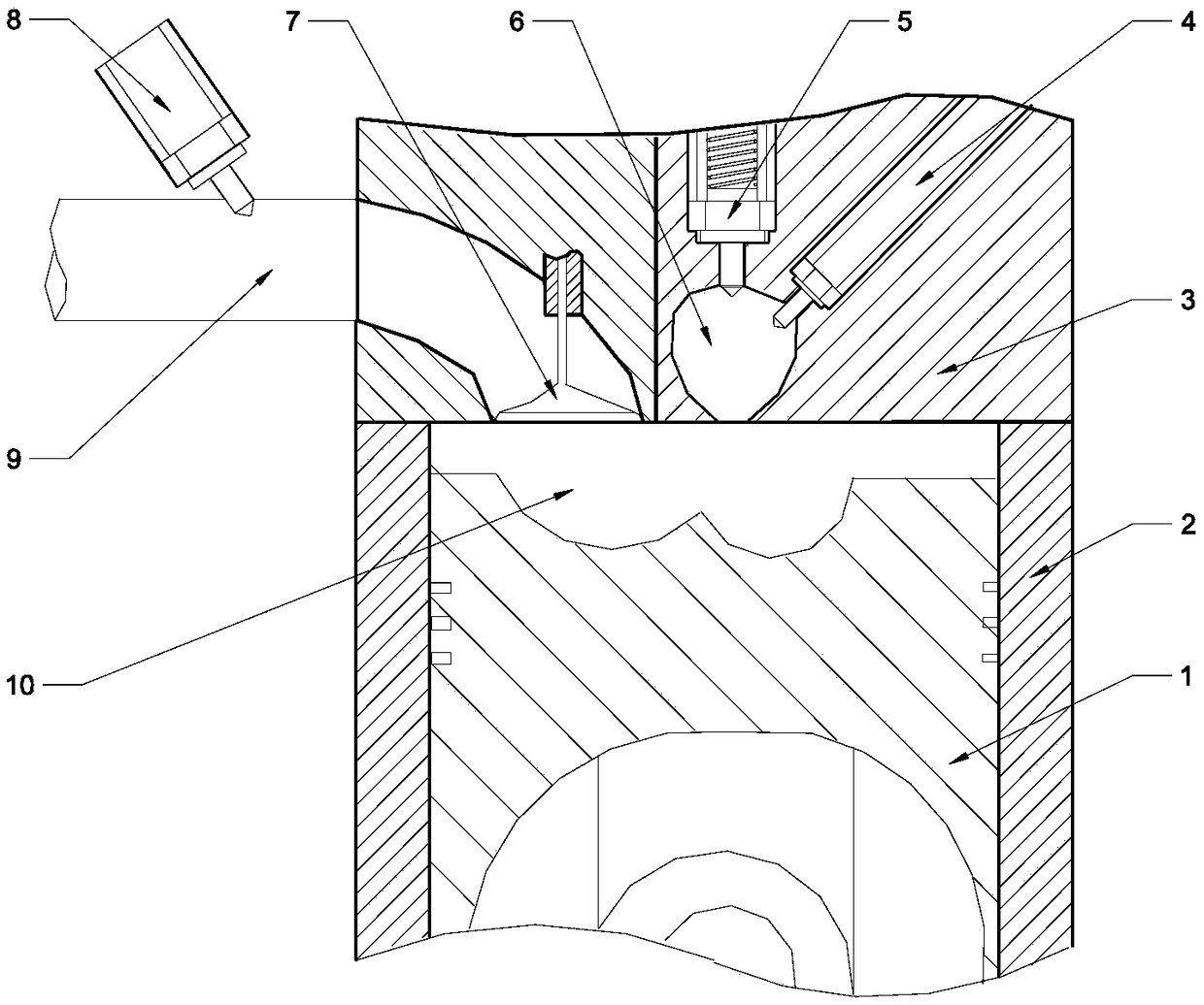
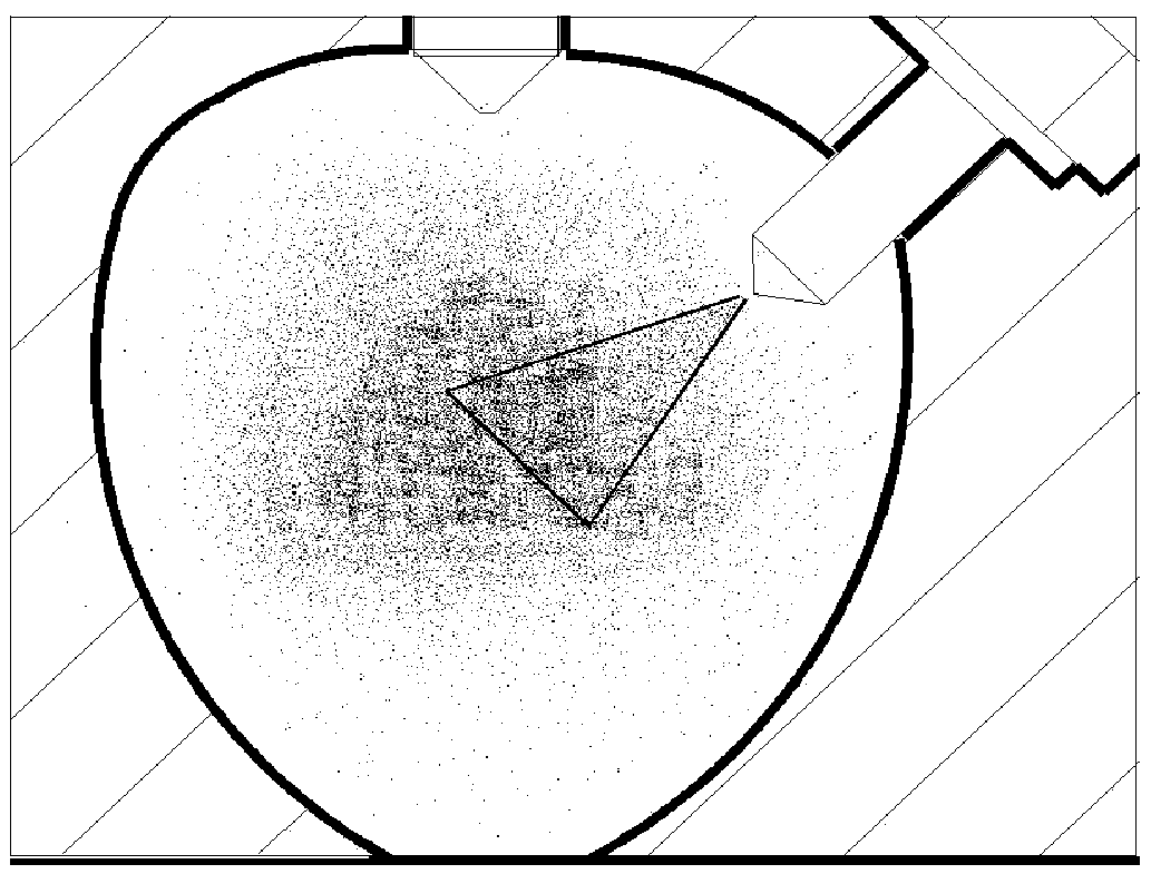
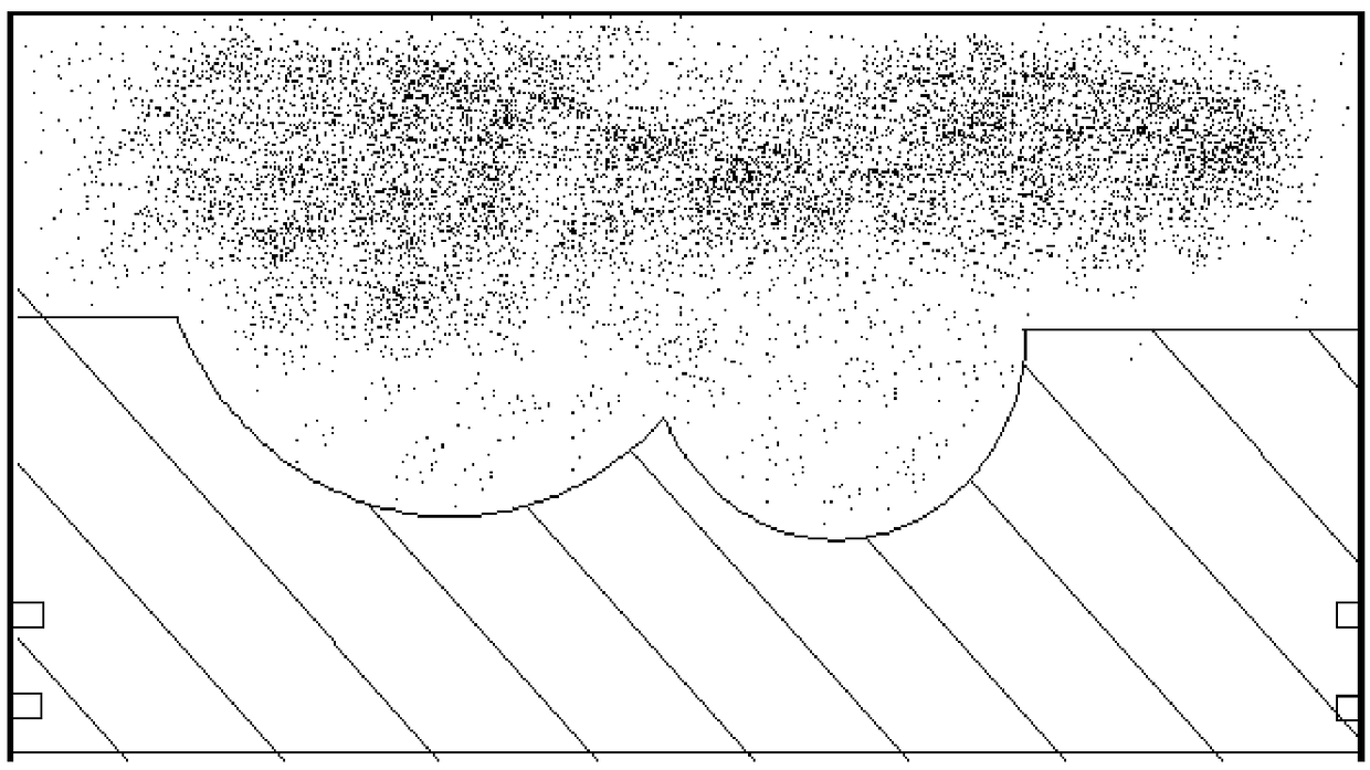
[0022] The present invention is described in more detail below in conjunction with accompanying drawing example:

[0023] combine Figure 1-6 The structure of the combustion system of the natural gas engine with premixed micro-injection ignition and low-pressure air supply in the pre-combustion chamber includes: piston 1, cylinder liner 2, cylinder head 3, fuel injector 4, low-pressure one-way air supply device 5, pre-combustion Chamber 6, intake valve 7, manifold low-pressure gas injection device 8, intake passage 9, main combustion chamber 10. The main combustion chamber is composed of the upper surface of the piston, the peripheral wall of the cylinder liner and the lower surface of the cylinder head; the pre-combustion chamber is located in the cylinder head and adopts an oval structure with a wide top and a narrow bottom. The central axis of the pre-combustion chamber coincides with the central axis of the cylinder. The outlet is located at the center of the bottom of th...


PUM


Abstract

The invention aims at providing a natural gas engine combustion organization method adopting manifold multiple-injection, pre-combustion chamber low-pressure gas supply and diesel oil micro-jetting ignition. A low-pressure air spraying valve is arranged on each cylinder air inlet manifold, under different stations, the jetting frequency and timing of the low-pressure air spraying valve are controlled, and therefore natural gas forms different degrees of concentration gradient distributions in a cylinder; a one-way air supply valve is arranged on the top of a pre-combustion chamber, a suction stroke supplies air to the pre-combustion chamber, an oil injector is arranged above the right of the pre-combustion chamber in an inclined manner, a compressor stroke does not spray the micro amount of diesel oil to the pre-combustion chamber, the diesel oil is subjected to spontaneous combustion to ignite the mixed air in the diesel oil, and high-temperature gas is injected into a main combustionchamber to ignite the mixed air in the cylinder. Through adjusting of the air supply pressure of a one-way valve, the amount of natural gas in the pre-combustion chamber is adjusted, the ignition stability under different stations is ensured, through manifold multiple-injection, in-cylinder lean mixture concentration layering and rapid combustion can be achieved, and the economy and emission of the engine can be improved.

Description

technical field [0001] The invention relates to a combustion control method, in particular to a natural gas engine combustion control method. Background technique [0002] At present, resources such as traditional oil are gradually being exhausted. At the same time, the environmental problems caused by the combustion of traditional fuels are increasingly being paid attention to by countries all over the world. It is imperative to find new alternative energy sources. As a green fuel with abundant reserves and clean emissions, the research on natural gas has attracted extensive attention from all over the world. [0003] The premixed intake air of natural gas engine is divided into single-point injection of intake manifold and multi-point injection of intake manifold. The single-point injection of intake manifold supplies air continuously throughout the engine cycle, which will cause a large amount of gas in the valve overlap angle. The escape of natural gas is not conducive ...

Claims


Application Information

Patent Timeline
IPC IPC(8): F02M45/08F02M43/04F02M61/04F02D19/06F02M63/00
CPCF02D19/0613F02D19/0647F02M43/04F02M45/08F02M61/04F02M63/0031Y02T10/12Y02T10/30
Inventor 杨立平何永恒姚崇宋恩哲孙军费红姿
Owner HARBIN ENG UNIV
Why Eureka
Try Eureka