Chloromethane copious cooling floating head type heat exchanger

A floating head heat exchanger and methyl chloride technology, applied in the field of heat exchange, can solve the problems of unfavorable heat exchange efficiency, inconvenient cleaning, large heat medium tube bundle, etc., and achieve the advantages of easy cleaning and disassembly, simple structure, and guaranteed sealing performance Effect

Pending Publication Date: 2019-01-11
ZHANGJIAGANG KEHUA CHEM EQUIP MFG
View PDF8 Cites 0 Cited by
  • Summary
  • Abstract
  • Description
  • Claims
  • Application Information

AI Technical Summary

Problems solved by technology

[0002] The heat exchanger realizes the heat exchange between the medium in the tube side and the shell side through the heat exchange tube. Most of the heat exchangers currently used are equipped with straight tube heat medium tube bundles. This kind of heat exchanger mainly has the following disadvantages: heat medium The tube bundle is limited by the tube length, so the length of the heat medium tube bundle is small, and the medium flows evenly in the straight tube, which makes the turbulence effect of the heat exchanger poor, resulting in insignificant heat transfer effect, which is not conducive to improving heat transfer efficiency
Most of the above-mentioned heat exchangers are floating head heat exchangers. The floating head needs to be disassembled for tube bundle cleaning, which is inconvenient to clean, and there will be a certain force between the tube plate and the cylinder at the floating head end, which is not conducive to the long-term stable heat exchange operation of the heat exchanger.

Method used


Image

  • Chloromethane copious cooling floating head type heat exchanger
  • Chloromethane copious cooling floating head type heat exchanger
  • Chloromethane copious cooling floating head type heat exchanger

Examples


Embodiment Construction

[0022] The technical solutions in the embodiments of the present invention will be described in detail below in conjunction with the accompanying drawings in the embodiments of the present invention. Obviously, the described embodiments are only some of the embodiments of the present invention, not all of them. Based on the embodiments of the present invention, all other embodiments obtained by persons of ordinary skill in the art without making creative efforts belong to the protection scope of the present invention.

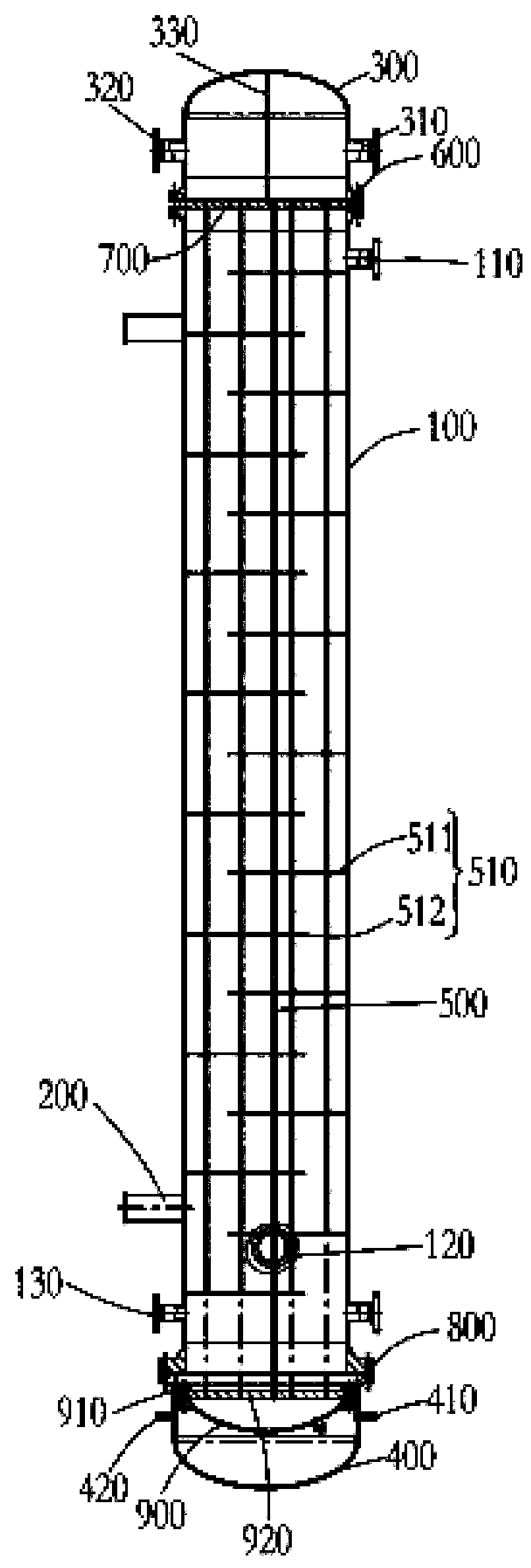
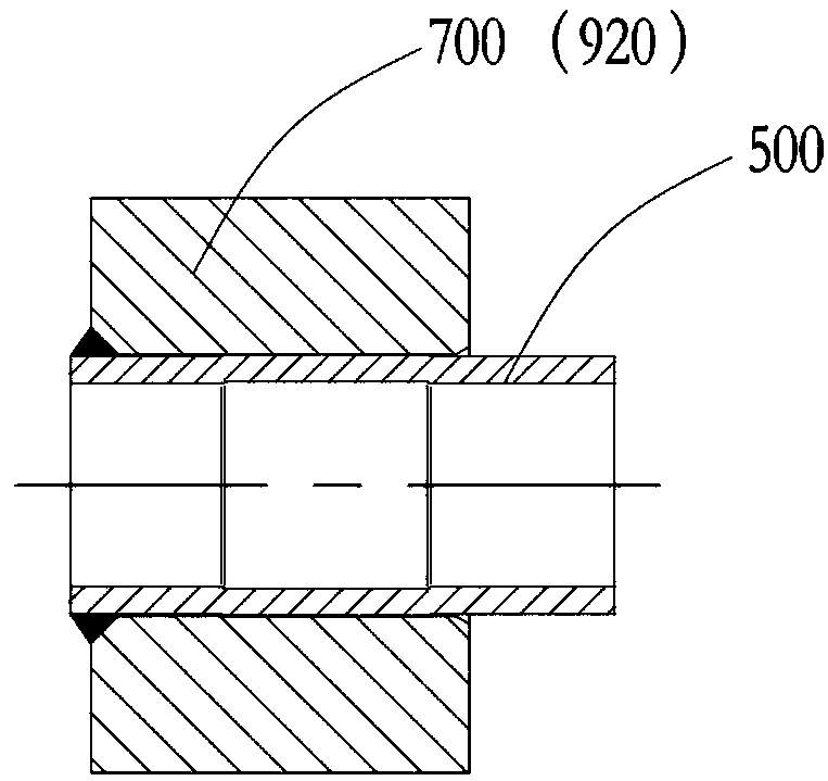
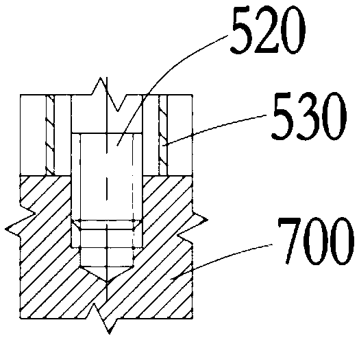
[0023] ginseng Figure 1 to Figure 6 As shown, the methyl chloride cryogenic floating head heat exchanger in this embodiment includes a housing 100, a support 200 fixed to the bottom of the housing 100, and a head 300 and an outer head cover 400 respectively arranged at both ends of the housing 100, The shell 100 is provided with a tube bundle 500, the head 300 and the shell 100 are connected by the first set of flanges 600, and the fixed tube plate 700 is arra...


PUM


Abstract

The invention discloses a chloromethane copious cooling floating head type heat exchanger, which comprises a shell, a supporting seat, a sealing head and an outer head cover. The shell is internally provided with tube bundles. The sealing head is connected with the shell through a first set of flanges. A fixing pipe plate is arranged between the first set of flanges. The fixing pipe plate is in mortise-tenon connection with a first flange. The contact surfaces of two end faces of the fixing pipe plate and the first set of flanges are correspondingly provided with first sealing rings. The shellis connected with the outer head cover through a second set of flanges. The second set of flanges is internally provided with second sealing rings. The outer head cover is internally provided with afloating head cover. A floating head pipe plate is arranged at the end, near the shell, of the floating head cover through hook rings. Two ends of each tube bundle are correspondingly fixed to the fixing pipe plate and the floating head pipe plate. A first liquid outlet and a liquid inlet are formed in the upper end and the lower end of the sealing head correspondingly. An air inlet, an air outletand a second liquid outlet are formed in the shell. A drainage opening and an emptying opening are formed in the upper end and the lower end of the outer head cover correspondingly. The chloromethanecopious cooling floating head type heat exchanger has simple structure and good sealing property.

Description

technical field [0001] The application relates to the technical field of heat exchange, in particular to a methyl chloride cryogenic floating head heat exchanger. Background technique [0002] The heat exchanger realizes the heat exchange between the medium in the tube side and the shell side through the heat exchange tube. Most of the heat exchangers currently used are equipped with straight tube heat medium tube bundles. This kind of heat exchanger mainly has the following disadvantages: heat medium The tube bundle is limited by the tube length, so the length of the heat medium tube bundle is small, and the medium flows evenly in the straight tube, which makes the turbulence effect of the heat exchanger poor, resulting in insignificant heat exchange effect, which is not conducive to improving heat exchange efficiency. Most of the above-mentioned heat exchangers are floating head heat exchangers. The floating head needs to be disassembled for tube bundle cleaning, which is ...

Claims


Application Information

Patent Timeline
Patent Type & Authority Applications(China)
IPC IPC(8): F28D7/16F28F9/02F28F9/12F28F9/24F28F9/26F28F9/00F28F9/06
CPCF28D7/16F28F9/005F28F9/0241F28F9/06F28F9/12F28F9/24F28F9/26
Inventor 顾国兴程凯顾聪
Owner ZHANGJIAGANG KEHUA CHEM EQUIP MFG
Why Eureka
Try Eureka