
Optical axis consistency calibration method of airborne multi-optical axis optical load

A consistent and multi-optical axis technology, applied in the field of optical calibration, can solve problems such as uncalibration, scattered distribution of multi-optical axis optical loads, and long distances in space, etc., to achieve light equipment, low labor intensity, and guaranteed calibration The effect of precision

Active Publication Date: 2019-01-11
CHANGCHUN UNIV OF SCI & TECH
View PDF8 Cites 8 Cited by
  • Summary
  • Abstract
  • Description
  • Claims
  • Application Information

AI Technical Summary

Problems solved by technology

[0008] However, this existing technology can only be used for the calibration of compact multi-optical axis systems. If the distribution of multi-optical axis optical loads is scattered and the space is far away from each other, this solution cannot be calibrated

Method used


Image

  • Optical axis consistency calibration method of airborne multi-optical axis optical load
  • Optical axis consistency calibration method of airborne multi-optical axis optical load
  • Optical axis consistency calibration method of airborne multi-optical axis optical load

Examples


Embodiment Construction

[0018] The specific scheme of the airborne multi-axis optical load optical axis consistency calibration method of the present invention is as follows.

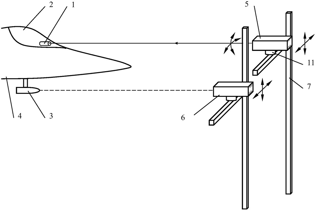
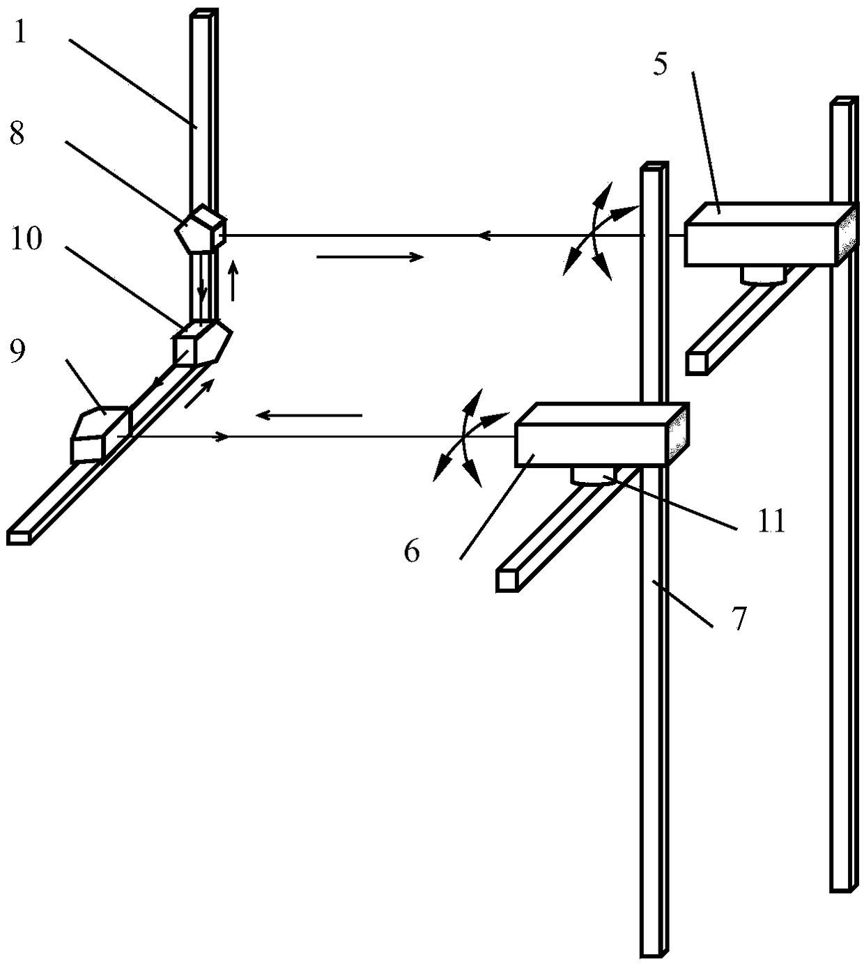
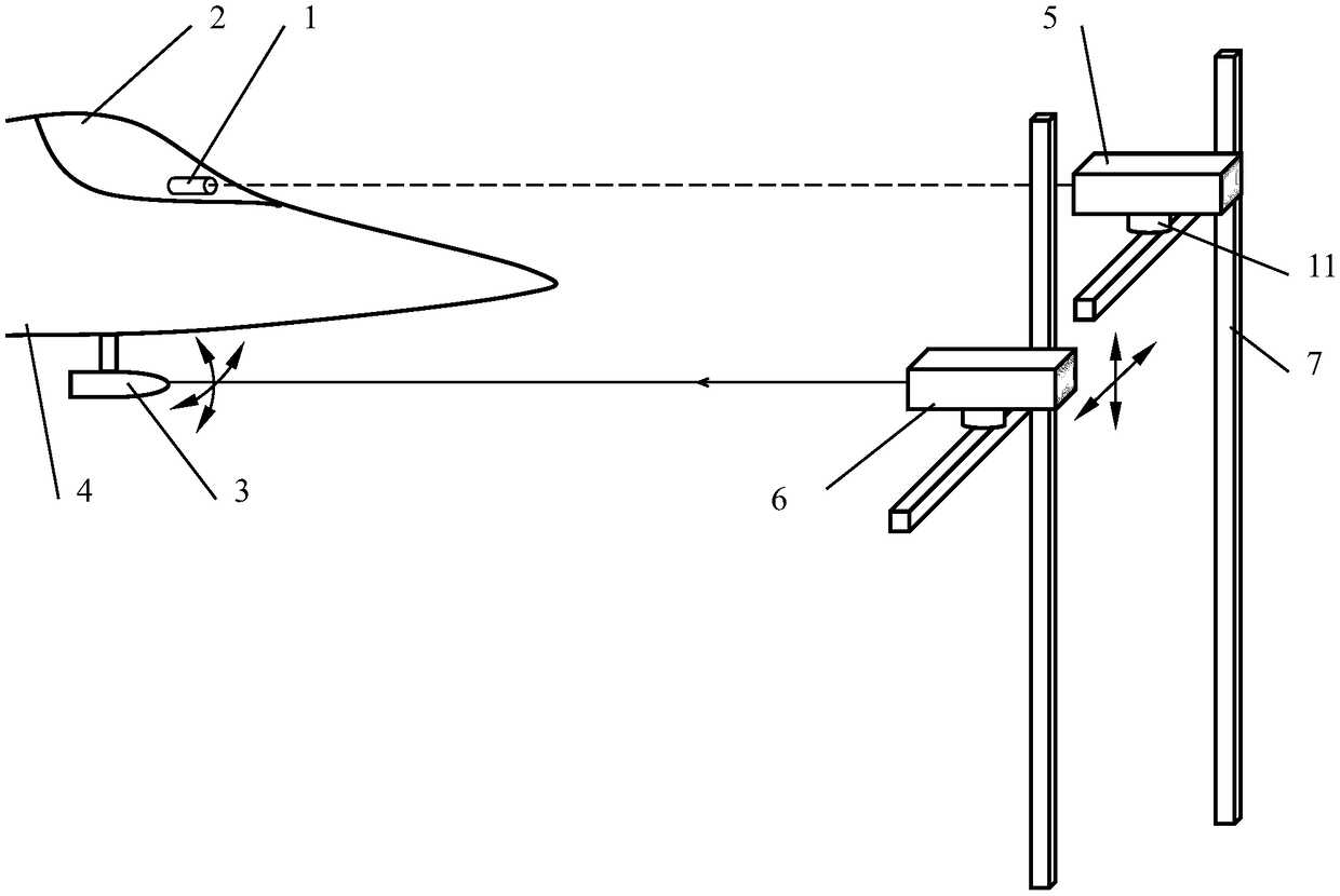
[0019] In the first step, install the main laser autocollimator 5 and the auxiliary laser autocollimator 6 on their respective right-angled two-dimensional slide rails 7, and arrange the main laser autocollimator 5 and the auxiliary laser autocollimator 6 In front of fuselage 4, such as figure 1 As shown, the main laser autocollimator 5 and the auxiliary laser autocollimator 6 adopt a digital high-precision laser autocollimator, and the built-in display can show the true image of the optical target; according to the airborne fire control system sight 1 and the design spatial positional relationship between the photoelectric pod 3, determine the spatial positional relationship between the main laser autocollimator 5 and the secondary laser autocollimator 6, further speaking, according to the airborne fire control system sight 1...


PUM


Abstract

The invention discloses an optical axis consistency calibration method of an airborne multi-optical axis optical load, and belongs to the technical field of optical calibration. The calibration operation of the prior art is complicated, the difficulty is large, and the labor intensity is high. The optical axis consistency calibration method comprises the steps of: arranging a main laser auto-collimator and an auxiliary laser auto-collimator in front of a machine body; making the optical window of an aiming device of an airborne fire force control system opposite to the optical window of the main laser auto-collimator, and making the optical window of the photoelectric pod opposite to the optical window of the auxiliary laser auto-collimator; completing the coaxial calibration of the aimingaxis of the airborne fire force control system and the optical axis of the main laser auto-collimator; completing the coaxial calibration of the optical axis of the auxiliary laser auto-collimator and the optical axis of the main laser auto-collimator; completing the coaxial calibration of the optical axis of a central photoelectric sensor and the optical axis of the auxiliary laser auto-collimator; and finally, completing the coaxial calibration of the optical axis of each photoelectric sensor and the optical axis of the auxiliary auto-collimator one by one. According to optical axis consistency calibration method, the optical axis consistency calibration can be realized by only adjusting the calibration device and the to-be-calibrated optical load.

Description

technical field [0001] The invention relates to a method for calibrating the consistency of optical axes of an airborne multi-optical axis optical load, which is used for calibrating the optical axis consistency of an airborne multi-optical axis optical load. The multi-optical axis optical load is a plurality of photoelectric sensors. The optical axis consistency means that the respective axes of several photoelectric sensors are parallel to the reference axis of the carrier plane, which belongs to the technical field of optical calibration. Background technique [0002] The sight 1 of the airborne fire control system is set in the cockpit 2, such as figure 1 As shown, the aiming axis of the fire control system is taken as the reference axis of the carrier aircraft. The airborne photoelectric stabilization equipment used in conjunction with the fire control system includes several photoelectric sensors, which are usually installed in a photoelectric pod 3, and according to ...

Claims


Application Information

Patent Timeline
Patent Type & Authority Applications(China)
IPC IPC(8): G01M11/00
CPCG01M11/00
Inventor 王春艳刘欢刘智王志坚
Owner CHANGCHUN UNIV OF SCI & TECH
Learn More