Automatic detecting device

A technology of automatic detection and equipment, applied in measuring devices, using repetitive force/pulsation force to test the strength of materials, instruments, etc., can solve problems such as safety accidents and large experimental errors, and achieve the purpose of reducing safety accidents, reducing errors, and being easy to replace. Effect

Pending Publication Date: 2019-01-11
KUNSHAN HAIWEI AUTOMATION
View PDF0 Cites 6 Cited by
  • Summary
  • Abstract
  • Description
  • Claims
  • Application Information

AI Technical Summary

Problems solved by technology

[0005] The purpose of the present invention is to provide an automatic detection equipm

Method used


Image

  • Automatic detecting device
  • Automatic detecting device
  • Automatic detecting device

Examples


Example Embodiment

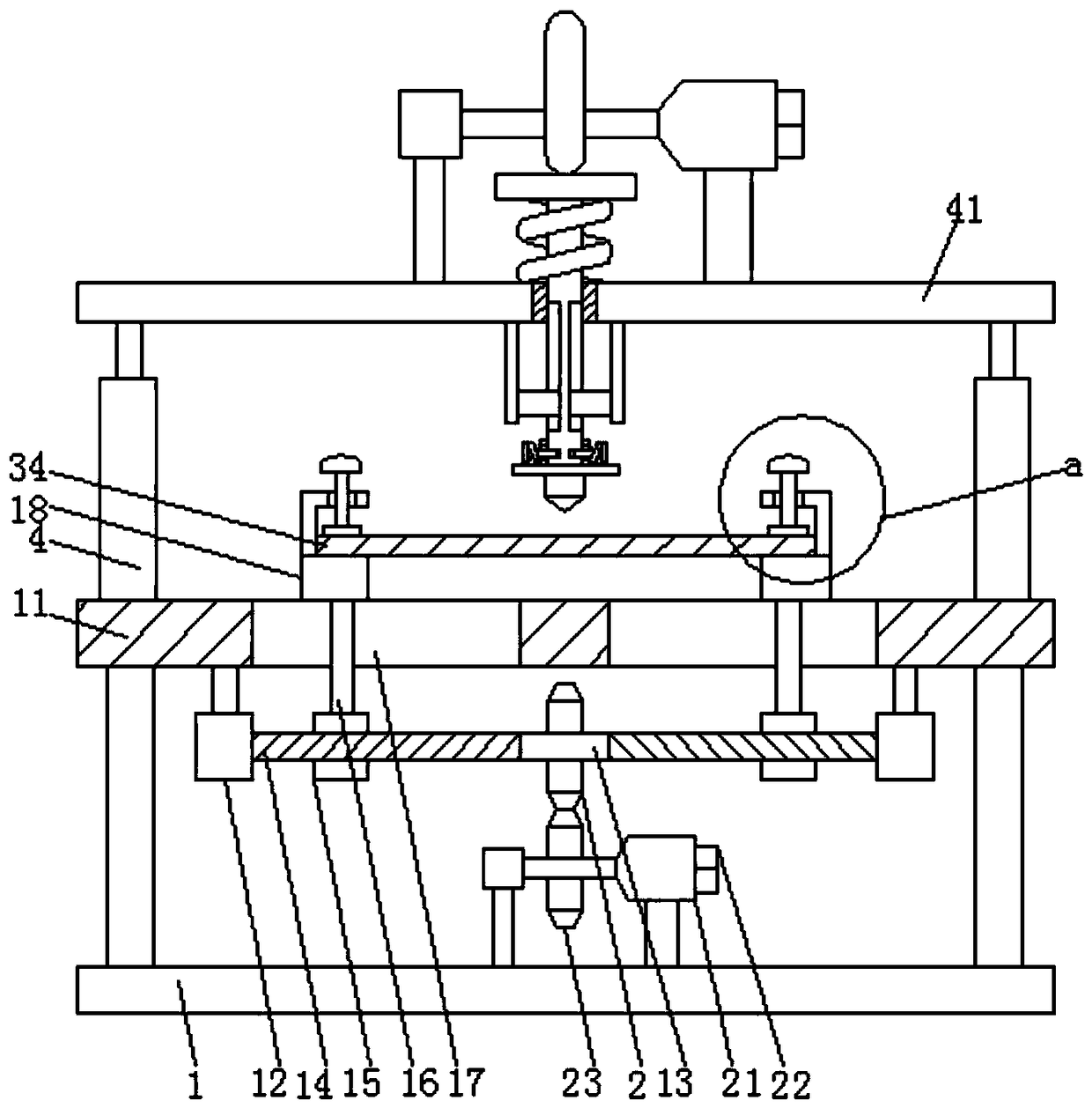
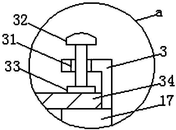
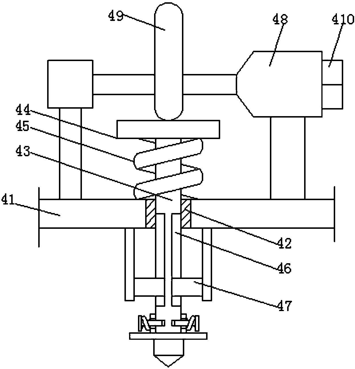
[0023] The technical solutions in the embodiments of the present invention will be clearly and completely described below in conjunction with the accompanying drawings in the embodiments of the present invention. Obviously, the described embodiments are only a part of the embodiments of the present invention, rather than all the embodiments. Based on the embodiments of the present invention, all other embodiments obtained by those of ordinary skill in the art without creative work shall fall within the protection scope of the present invention.

[0024] In the description of the present invention, it should be understood that the terms "longitudinal", "lateral", "upper", "lower", "front", "rear", "left", "right", "vertical", The orientation or positional relationship indicated by "horizontal", "top", "bottom", "inner", "outer", etc. are based on the orientation or positional relationship shown in the drawings, and are only for the convenience of describing the present invention, r...


PUM


Abstract

The invention discloses an automatic detecting device. The automatic detecting device comprises a base. The upper end of the base is arranged with an operating platform. The lower end of the operatingplatform is arranged with a shaft seat. The shaft seat is arranged with a linkage shaft. The two sides of the linkage shaft are both arranged with threaded protrusions. The surfaces of the threaded projections are threadedly connected with threaded sleeves. The threaded sleeves are arranged with limiting rods. The limiting rods are slidably connected with the limiting holes arranged on the operating platform. The upper ends of the limiting rods are arranged with supporting tables. According to the automatic detecting device, the glass plate can be effectively fixed through two clamping baseswhich can be moved away or close to one another, so that the assembling efficiency is improved; the glass plate can be stroke by the knocking head in a reciprocating constant force by extruding the extruding plate through a cam, so that the error of the experiment data is reduced.

Description

Technical field [0001] The invention relates to the technical field of mechanical equipment, in particular to an automatic detection equipment. Background technique [0002] After the glass plates are mass-produced, each batch of glass plates needs to be sampled and tested to determine the qualified quality. [0003] 1. The traditional detection method mostly uses a hammer to perform percussion experiments. Because the force of the hand is different each time, it is easy to cause errors in the experimental data; [0004] 2. Knock the glass at close range, if the glass breaks, it is easy to cause a safety accident. Summary of the invention [0005] The purpose of the present invention is to provide an automatic detection equipment to solve the problem of large experimental errors and the problem of causing safety accidents. [0006] In order to achieve the above objective, the present invention provides the following technical solutions: an automated testing equipment, including a base...

Claims


Application Information

Patent Timeline
IPC IPC(8): G01N3/34G01N3/02
CPCG01N3/34G01N3/02G01N2203/0005G01N2203/0039
Inventor 杨玉清
Owner KUNSHAN HAIWEI AUTOMATION
Why Eureka
Try Eureka