A projector

A projector and projection lens technology, applied in the field of projectors, can solve the problems of slow brightness decay, affecting look and feel, image clarity, and insufficient brightness, and achieve the effect of improving brightness and contrast, and improving the utilization rate of light.

Inactive Publication Date: 2019-01-11
深圳小淼科技有限公司
View PDF17 Cites 6 Cited by
  • Summary
  • Abstract
  • Description
  • Claims
  • Application Information

AI Technical Summary

Problems solved by technology

[0003] In the process of realizing the present invention, the inventors have found that there are at least the following problems in the above related technologies: Compared with DLP digital technology projectors (DLP projectors, the brightness attenuation is slower and the contrast ratio presented is higher), the single-chip LCD projection Although the instrument is

Method used


Image

  • A projector
  • A projector
  • A projector

Examples


Example Embodiment

[0030] The present invention will be described in detail below in conjunction with specific embodiments. The following examples will help those skilled in the art to further understand the present invention, but do not limit the present invention in any form. It should be noted that those skilled in the art can make several modifications and improvements without departing from the concept of the present invention. These all belong to the protection scope of the present invention.

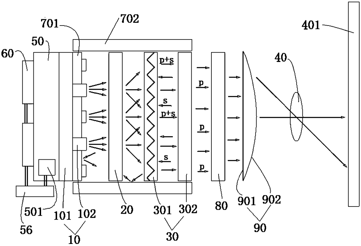
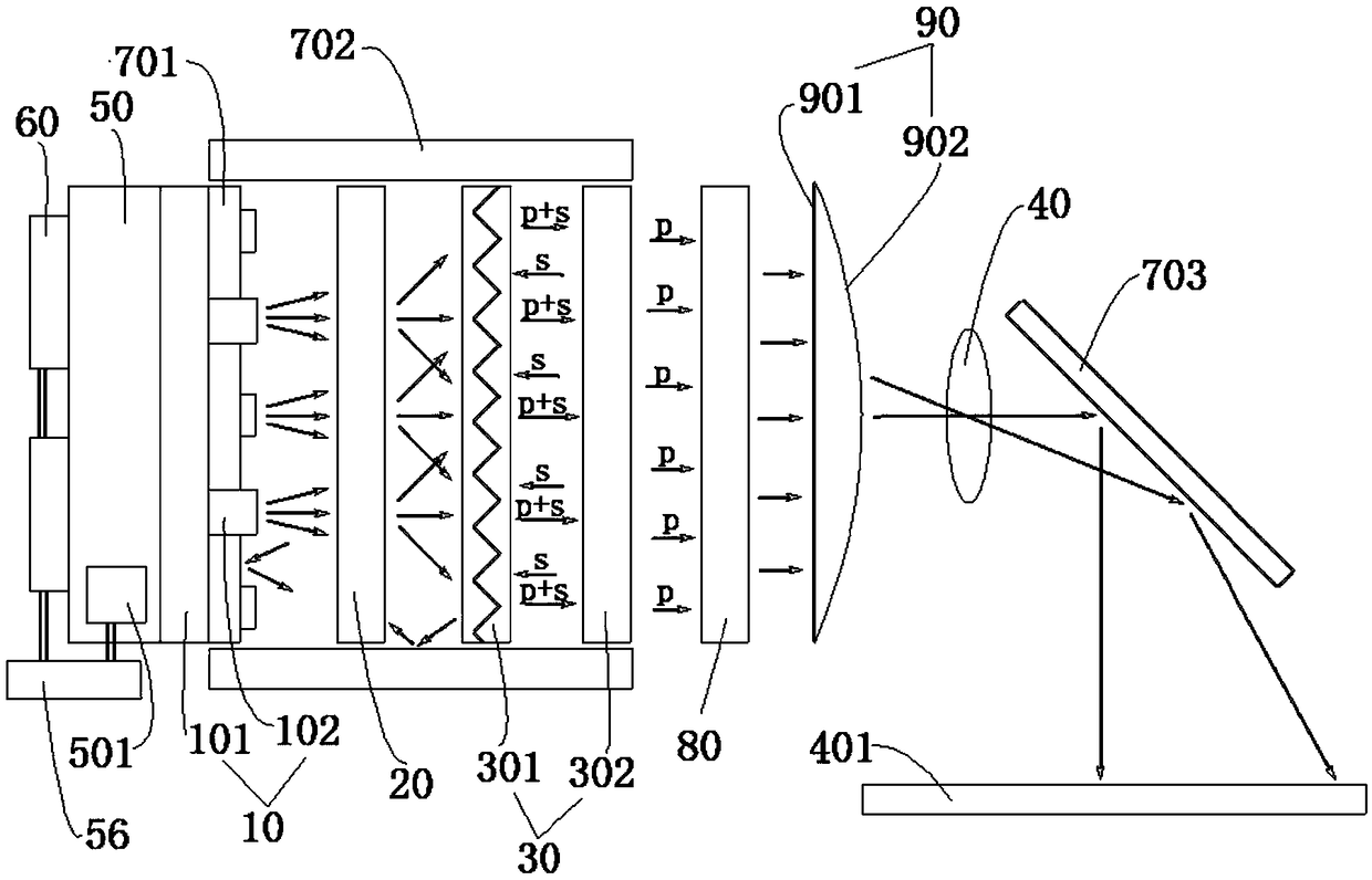
[0031] In order to facilitate the definition of the connection structure, the present invention defines the position of the components with reference to the direction of the light path. For example, the surface light source 10 is the head of the projector, and the surroundings along this direction are the "side" or "surrounding" directions, and the light from the surface The direction in which the light source 10 passes through the diffusion plate 20 is the “front” direction, and the direction in w...


PUM


Abstract

The invention discloses a projector in the field of optical path design. The projector mainly includes a surface light source 10, a diffusion plate 20, a light intensifying sheet 30 and a projection lens 40, wherein the surface light source 10, the diffusion plate 20, the light intensifying sheet 30 and the projection lens 40 are arranged in sequence. The light source outputted from the surface light source 10 is diffused through the diffusion plate 20, and then subjected to the dimming treatment by the dimming sheet 30, and then inputted into the projection lens 40. The projector 1 further includes a heat sink 50, a fan 60, a controller 56, a first mirror 701, a second mirror 702, an LCD 80, and a Fresnel lens 90. The projector of the invention can obtain high-brightness and high-contrastimaging in the above manner, and solves the problem that the imaging of the traditional monolithic LCD projector is not clear enough, the brightness is not high and is not uniform.

Description

technical field [0001] The invention relates to the field of optical path design, in particular to a projector. Background technique [0002] At present, the traditional single-chip LCD projector (liquid crystal projector) is very similar to the principle of the traditional movie projector or slide projector, that is, a piece of LCD color liquid crystal screen is used as the source of the image at the position where the original movie film or slide is located. , through the high-power bulb or LED lamp on the back for strong light projection, then through the Fresnel lens to shape the light, display the image, and trapezoidal correction, etc., and finally through the special magnifying lens of the projector, the image on the LCD screen with high brightness , enlarged and projected onto a white screen or wall, enabling users to obtain an image of tens to hundreds of inches in size, which is very similar to the effect and experience of watching a movie. The traditional single-...

Claims


Application Information

Patent Timeline
IPC IPC(8): G03B21/20G03B21/16G03B21/00
CPCG03B21/006G03B21/16G03B21/2013G03B21/2033G03B21/2053G03B21/2066G03B21/208
Inventor 韦斌何学苗翁清
Owner 深圳小淼科技有限公司
Why Eureka
Try Eureka